|
||

|
|
||||||||||||||||||
|
#1
 23-07-2010
|
|||
|
|||
 K2 V2 Almost a year and half later I am revisiting this project. You can find the first one here.. http://teamkassanova.webs.com/k2page1.htm . I had alot of problems with that version and so its time fore a complete redesign. My goal is to create a buggy which is more durable , has the lowest center of gravity of any 2wd buggy, and to make it handle as good or better than the other factory buggies. Secondary goals include getting it into a magazine and having it be raced at the Ifmar worlds. (Shooting high) The rear will be made with a Team Magic E4 drive train and suspension mounts along with custom delrin a-arms and ntc3 rear hub carriers. I will be adding a custom slipper clutch in there too. The reason behind the team associated ntc3 hub carriers is for pure durability. My buggy will probably end up being heavier than the others but it will break less and with the new lipo and brushless technology it shouldn't be a huge deal. Their is a possiblty the I might start by making a simple version first by just using the stock B4 suspension parts and stand up shocks to see how this electronics layout does. But it hasn't been decided wither I will take smaller steps or just go all out. The chassis will be made out of carbon fiber and have horizontal saddle packs. I am going to be trying to use screws thru-out the whole buggy with the same hex size so I will only have to use one or two wrenchs on it. Up front I will be using B4 steering and a Gt2 front chassis plate. I wanted to have my front a-arms be stronger than stock B4 a-arms so I will be making beefier custom delrin a-arms (lower and upper) and ntc3 front hub carriers also for durability. The buggy will feature laydown shocks all around. I am choosing to use laydown shocks because they provide a lower center of gravity, added durability, and a progressive suspension. My current idea is to use revo shocks on the buggy to provide a smoother suspension on the big jumps because of there larger diameter. They may end up being too long though.. in which case I may have to use touring car shocks. The receiver and esc will be mounted behind the rear axle in a battery box to provide some weight to the rear and to keep all the electronics down the center. They may also be mounted on each side of the chassis. I also have a highly top-secret innovation I will be using on this buggy. Here is a Cad drawing I did just to get an idea of spacing and of how it will look and such. The cad drawing definatly isn't done and I will probably just start making actual progress on the buggy instead of finishing the cad drawing. So far I have alot of B4 parts left over from the K2 v1 and have the Nitro Tc3 hubs and Gt2 front plate..and I got a great deal on the E4 parts so those should be here soon and I can start working on drawing up the chassis. 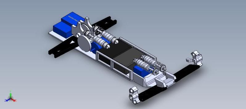 Ethan 
|
|
#3
23-07-2010
|
||||
|
||||
|
Hey, good luck with this one, I was following the build of your previous car and wondered recently what you were up to now.
You should finish the CAD drawing first, much better testing all the suspension and drivetrain on the computer than half building it and finding it doesn't work, then having to go back and remake new parts because they need changes.
|
|
#4
23-07-2010
|
||||
|
||||
|
Look awesome !
Good luke !!
__________________
Tamiya F103 - Hobbywing 13.5 - Hobbywing 1S Tamiya TRF201 - PRT HS 10.5 - Tekin RS Pro http://rctouch.over-blog.com/
|
|
#5
23-07-2010
|
|||
|
|||
|
Quote:
Quote:
I have been teaching myself Solidworks and so its been a trial and error type of thing I haven't grasped the advanced skills to draw a complete car and do tests on it..with my Cad skill level I find it more effective personally to get into the workshop and do trial and error by building. I received the Revo/Slayer shocks today. I got a good deal on them on ebay only $13 shipped for 4 slightly used shocks. In version 1 I had a hard time setting up the suspension with the touring car shocks. I'm not sure they where up to the task of offroad car. I picked Revo shocks because of there large diameter (14mm) and spring selection. Traxxas offers springs for the Revo shocks made for the Revo, Slayer , and Jato. The Revo shocks obviously being the stiffest and the Jato ones being the softest. These are a bit heavier than the stock B4 shocks but not too much. If weight becomes an issue I can always get the plastic Jato shocks. Here are some comparison pictures. On the far right are B4 shocks, middle are the Revo shocks, and the far left are touring car shocks I used on version one. I may resort back to the touring car shocks if the revo shocks are too heavy or big. But I think the added diameter and new spring choices will help a ton. Front 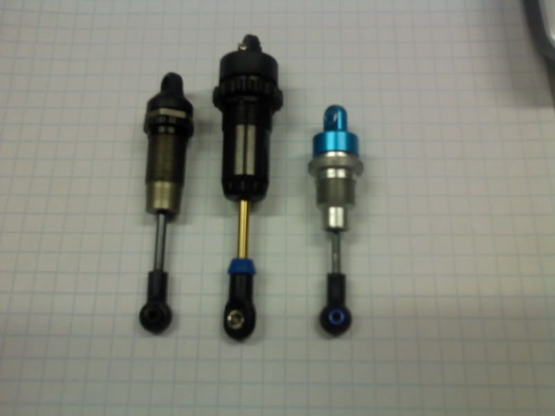 Rear 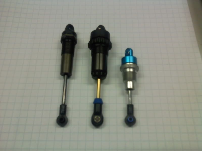
|
|
#6
24-07-2010
|
||||
|
||||
|
A good choice of shocks would be the ones from the Yokomo Bmax4, check them out!

__________________
Martin Sørlie, 1985. Spektrum DX4R Pro - TLR 22 2.0 & TLR 22-4 - Absima Team Smallsize
|
|
#7
24-07-2010
|
|||
|
|||
|
Hmm I will have to look into those.
Got the E4 parts today. I got an amazing deal for $55 shipped. I just have to get a rear E4 diff for it though. The e4 rear end is going to work great on this. The width of the hinge pins is slightly less than the B4. I was able to fit stock b4 a-arms on but the spur gear would hit the front of the a-arm with out modification so it looks like I will definatly have to make new a-arms. I was worried that I would have to make the wheelbase longer because of the lack of the room for the saddle pack but it looks like their will be plenty of room. I'm going to start drawing up the chassis and then I'll make a mock up chassis before I cut it out of some nice carbon. I feel like I almost need to figure out how to make a slipper clutch for this to get that out of the way though becuase thats one of the major hurdles I have to clear. I'll see what I can master mind. After getting the E4 aluminum parts I have the feeling this is going to end up a sort of "luxury" buggy . Here are some pictures.. 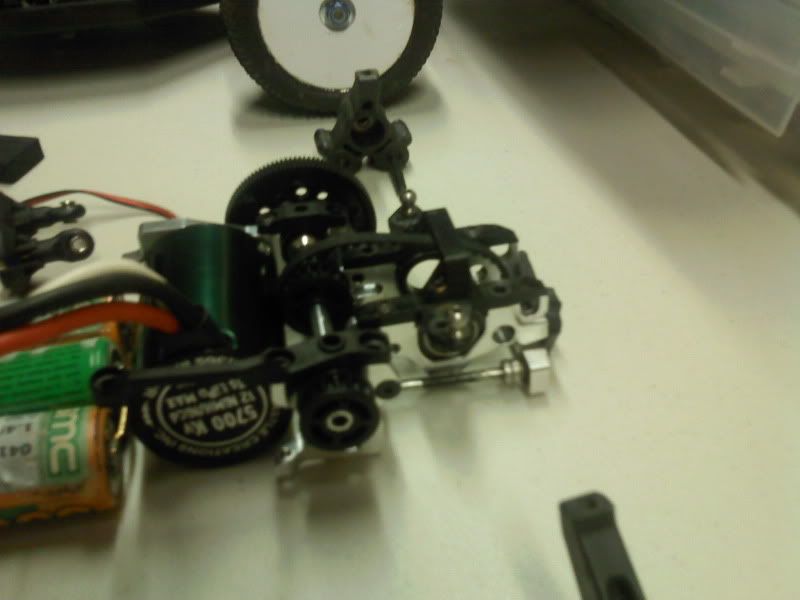 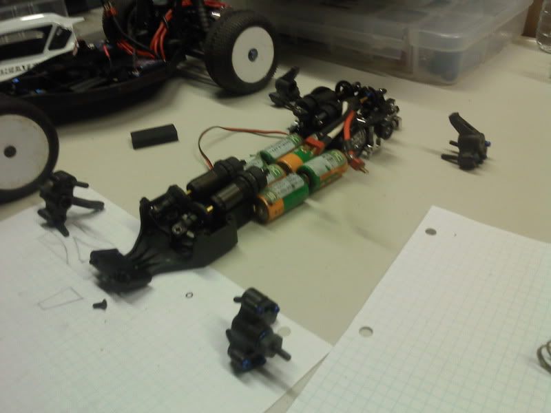 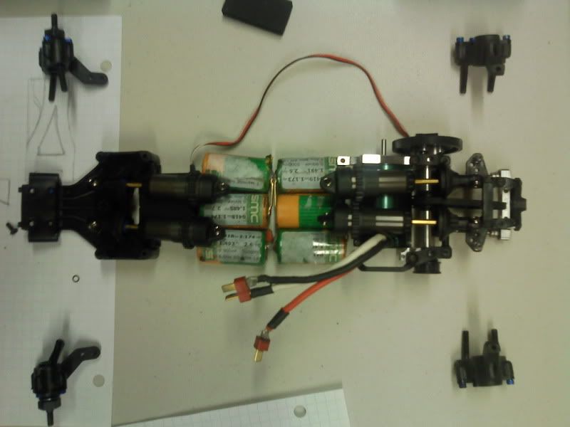
|
|
#8
24-07-2010
|
||||
|
||||
|
The slipper will be a big issue !
Good luke !
__________________
Tamiya F103 - Hobbywing 13.5 - Hobbywing 1S Tamiya TRF201 - PRT HS 10.5 - Tekin RS Pro http://rctouch.over-blog.com/
|
|
#10
25-07-2010
|
||||
|
||||
|
Lots of central weight there should make for good performance, yes?
__________________

|
|
#12
02-08-2010
|
|||
|
|||
|
Garry: Yes I believe that will help with handling.. the only worry is traction. I will be racing on a clay track so hopefully it will hook up
Jason: Yea the compact electronics make sense to me.. it allows for the car to transition quicker. I made a mock up chassis out of 1/8" lexan today. This material works great as mock up material because its clear and is very easy to work with. Not to mention inexpensive. The final chassis will of course be made out of 3mm Carbon fiber. Next I will be working on some mock up a-arms out of 3/8" lexan. The final a-arms will be made out of 8mm thick delrin. To give a comparison b4 front a-arms are almost 7mm thick and the rear a-arms are 8mm thick. Oh yes the nimh packs and mamba motor in the pictures are just for mock up reason.. I will be using a lipo saddle pack and a 13.5 motor. 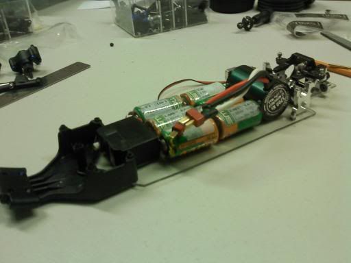 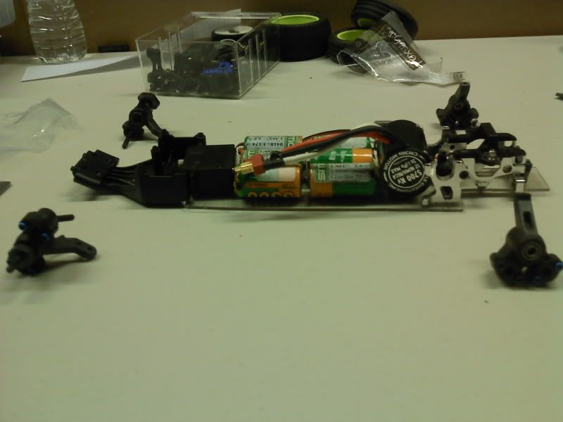
|
|
#13
07-08-2010
|
|||
|
|||
|
Got off work early today so I got some progress made. I made the mock-up front a-arms.. they definatly aren't perfect but they will do as mock ups.
I also got a lexan chassis brace done and the quick release battery door done today. I wanted to try something new.. and eveyone is posting everything on youtube these days so I decided to try a video blog of my progress on the buggy. Please excuse all the "um's'" haha http://www.youtube.com/watch?v=z76gzu-5Q7s Here are some pictures: 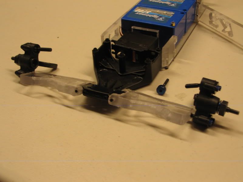 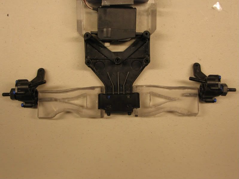 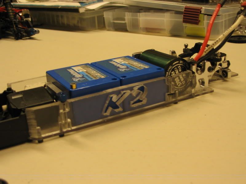 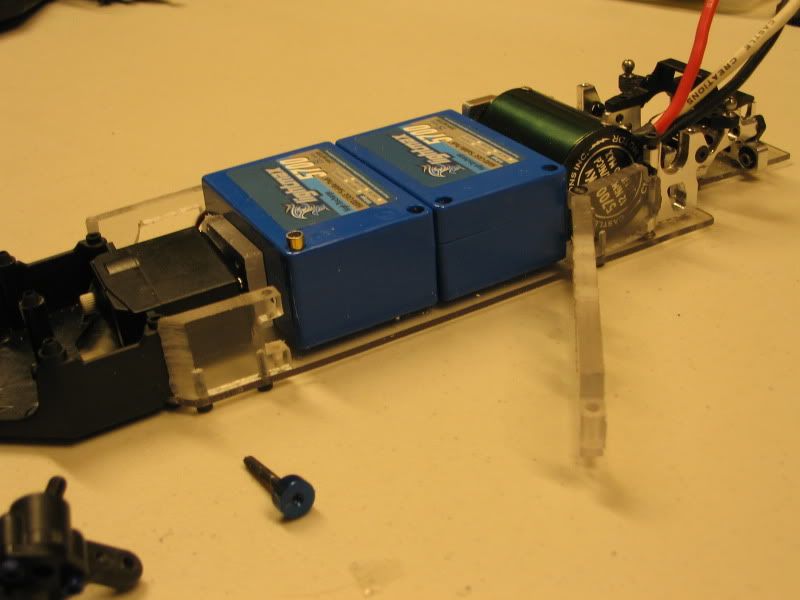 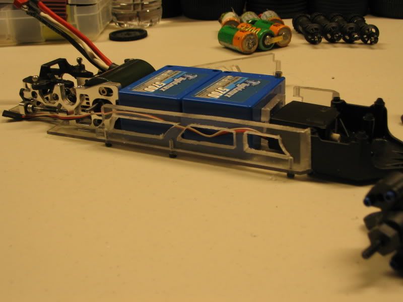
|
|
#15
27-11-2010
|
|||
|
|||
|
With the fear that my last electronic layout would not have enough rear traction I decided to redesign the chassis and turn the lipo saddle sideways like has been seen in some of the other mid-motor buggies. This pushes more of the battery weight towards the rear and will allow me to squeeze the esc and receiver onto the chassis between the batteries and servo. I think that even though this electronic layout will be similar to other mid-motor buggies their will be many other features that will make it unique.
Today I ordered a 3mm carbon fiber chassis from Rcfoam for $55 shipped. While that is in transit I will be working on trying cut another mock chassis out of lexan just to make sure the drawing is correct. I have moved my deadline to end of December/beginning of January. I want to have some time to test and tune the buggy before the big race that it will be debut at in early February. Here is the new chassis drawing. 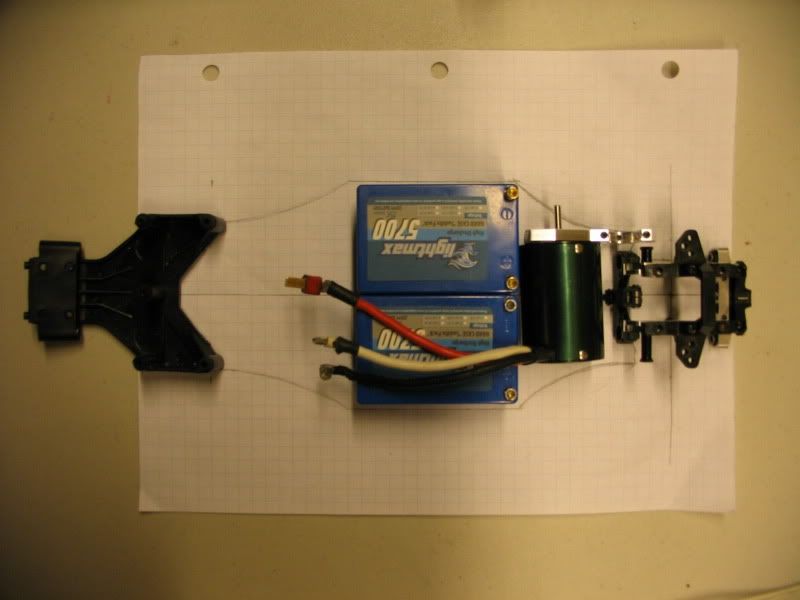 Ethan Team Kassanova
|
|
#16
03-12-2010
|
|||
|
|||
|
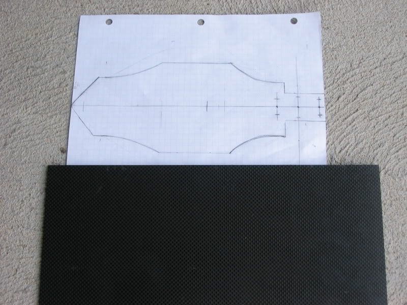
Today I received my piece of 3mm Carbon fiber for the main chassis and other parts. I got it from Rcfoam for $55 shipped. Since it is so expensive I'm going to have to be very careful not to mess up when I'm cutting the chassis. I will be cutting it with a hand-held jigsaw. The piece is very stiff and light..so definatly a good quality of carbon fiber. Next I'm going to prep the piece for cutting by covering it with painters tape. I have to make a few double checks on the chassis drawing then it will be ready to be taped to the piece of carbon with packaging tape and then the cutting will begin.
|
|
#17
08-12-2010
|
|||
|
|||
|
Change of plans..
I will be cutting the chassis out of 3mm aluminum first becuase of my uncertainty with the amount of traction this mid-motor layout will provide. I don't want to cut a chassis out of carbon then find out I have to redesign it and make another chassis. I will be continuing with the planned layout for now.. I will test it and if it doesn't have enough traction I will try moving half of the saddle pack behind the diff in a custom protective case. During the testing I will be comparing the car to my B4 buggy. If the layout of the B4 seems to be performing better I will go back to a traditional layout with a rear-motor but will still have a laydown suspension, strong a-arms, and hubs, 12mm hexs, etc. Once I'm sure that a certain layout will work then I will end up cutting the chassis out of the carbon fiber I was able to cut and drill the chassis yesterday. I think it turned out pretty good. With some more filing I think it will work nicely for testing. 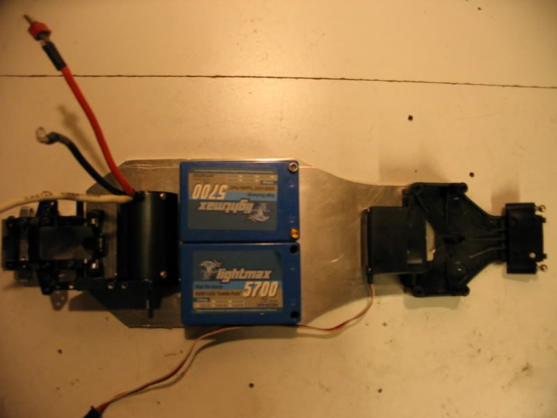 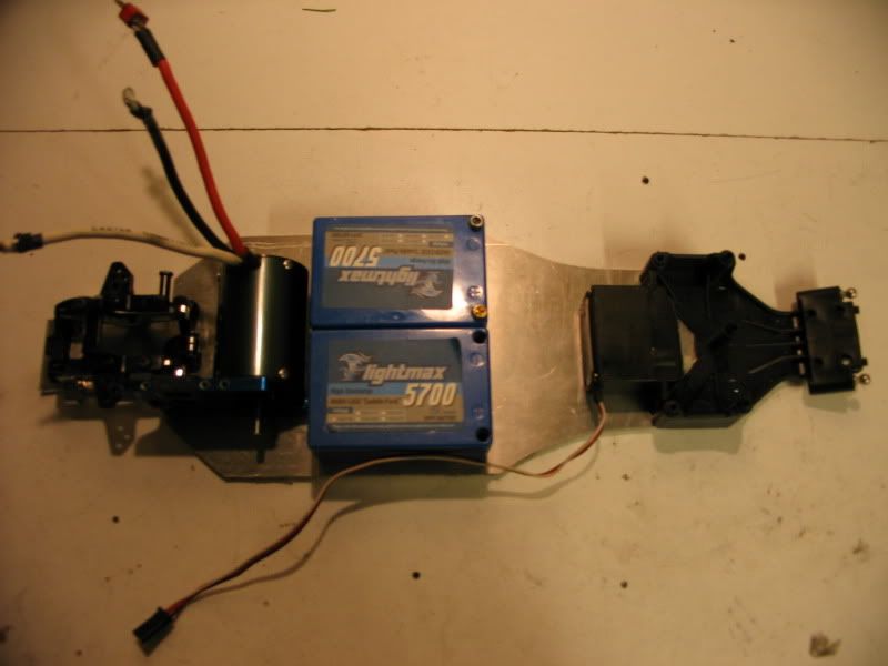 I have been hurrying to get my design for the a-arms finalized so that I can 3d print them at school before Christmas break. I am pretty close.. have a few small changes but this is what they will look like. When they are 3d printed the parts that are thick will actually be skinnier then they look. I had to make them pretty thick in area's becuase ABS plastic isn't the strongest stuff. I might eventually look at getting them milled out of delrin. But I'm hoping these will hold up. 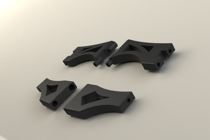
|
|
#18
08-12-2010
|
||||
|
||||
|
|
|
#19
10-12-2010
|
|||
|
|||
|
J.M: I have looked into useing those a-arms. Unfortunatly they are way too wide at the bulkhead for the B4 bulkhead and the rear E4 a-arm mounts. I was considering finding some bulkheads that would work but there's all kinds of problems that come up with using those a-arms. With making my own a-arms I have a lot of flexibility and can make them work perfectly with my design.
Talked to my Tech ed teacher today about the cnc mill we have at the school. He said it can do plastic and it appears to be 3-axis. They just haven't done alot with it becuase its brand new and they haven't had a ton of time to work with the programs and such.. so their is a possibility that if I can learn how to program the mill I can make milled delrin parts which would be alot stronger then Abs 3d printed parts AND stronger then composite a-arms such as the one's found on the B4. I'll have to look into this possibility more seriously. I gave my teacher my Solidworks drawing for the rear a-arms and he is going to print one of them early next week so I can make sure it fits. Today I got a lipo cradle done. The car will have a upper chassis so the battery is going to be slid in thru the side and the upper chassis will hold it down. I'm going to be making a quick release battery door such as the one I made earlier on with my original design.The esc and receiver look like they will fit perfectly right behind the servo. I cut the cradle slightly to large around the edges around the chassis so after I get it bolted to the chassis I will use the aluminum chassis as a guide and cut the over-hang off with the scroll saw for a nice even edge. I think it will look much nicer when installed on the final Carbon chassis. 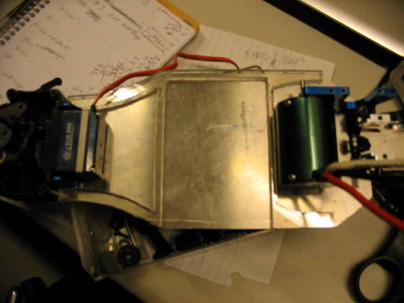
|
|
#20
13-12-2010
|
|||
|
|||
|
A mock rear a-arm was printed today so see if everything fits. Their are a few small changes I need to make with the spacing and sizes of the holes but for the most part it turned out great. The finish surface isn't the smoothest in some spots but with a slight amount of sanding it became smooth. I'm also think I will make the center section of the a-arm thicker since I don't think its quiet wide enough.
I'm going to get a final drawing done of the rear a-arms and get the front a-arm design ready for printing too. A nice feature about the a-arms are they can be used on either the right or left so I don't have to have as many spares. 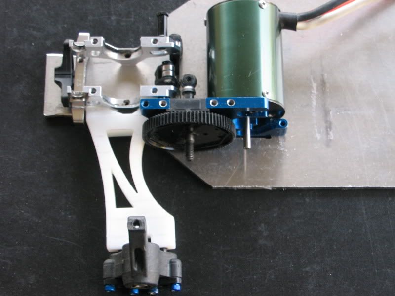 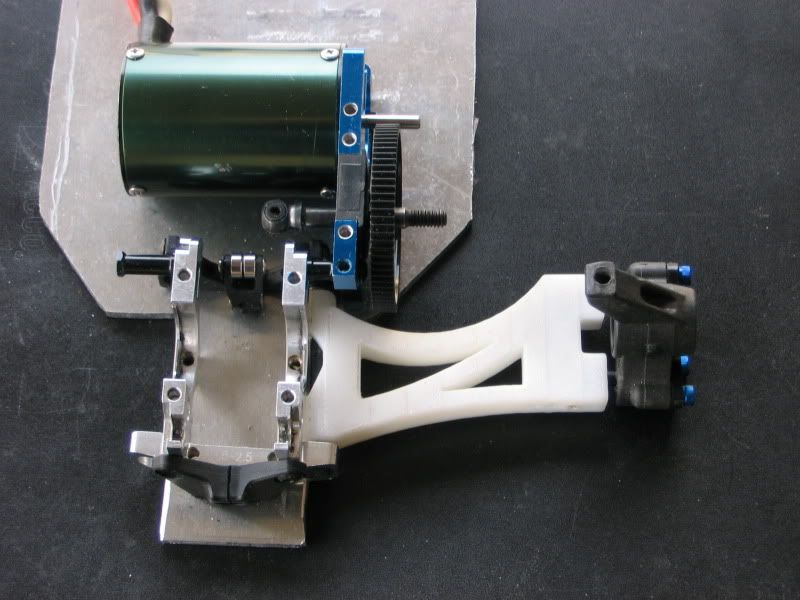
|
 |
|
|


 Linear Mode

