|
||

|
|
||||||||||||||||||
|
#121
 11-08-2012
|
||||
|
||||
|
Quote:
 I really appreciate the support from people at the event: I really appreciate the support from people at the event:1. Cool responses and advice as how to improve the car or what could be worth trying out on it. 2. Video and photo footage! 3. The support on getting the car up and running (when it broke down). Break down? Yes, it did. The end of the video shows the car sagging, and it was one of the ball connector nuts undoing themselves of the screw (no loctite, woops)! However, I had some breakage of 3D printed parts - hence why I was not jumping the car. I hope though it still gives an impression about the car. Some info about track, conditions, car and setup: Track & Conditions: Clay surface, dry, very bumpy and quite dusty. Car: 12T/3100kV Motor, Sensorless Total weight: 1470 grams (just a few grams too light for BNK regulations). Weight on front: Approx 1100 grams. Weight on rear: Approx 370 grams. (For comparison, my TRF201 was 1560 grams in total, 1030 grams on the rear, 530 on the front). Setup: Front Tires: Proline Caliber M3 (nearly new) Front damping: #300 oil (Tamiya) Front spring: Associated 'Rear' Red Rear Tires: Proline Holeshot M3 (nearly worn down to slicks) Rear damping: #300 oil (Tamiya) Rear spring: Associated 'Front' Blue The setup proved to have too little damping (not surprisingly actually, I just threw them on there on the build, my TRF201 uses #400 oil on the rear and #500 on the front. The springs seem slightly too soft up front, and I may need softer ones on the rear. I don't know how visible it is in the video, but from the rostrum you could see the rear wheels bouncing like they were on drugs  PS: The applause was for finishing the first lap, as the first time they saw it run it broke down on the first jump! 
|
|
#123
13-08-2012
|
||||
|
||||
 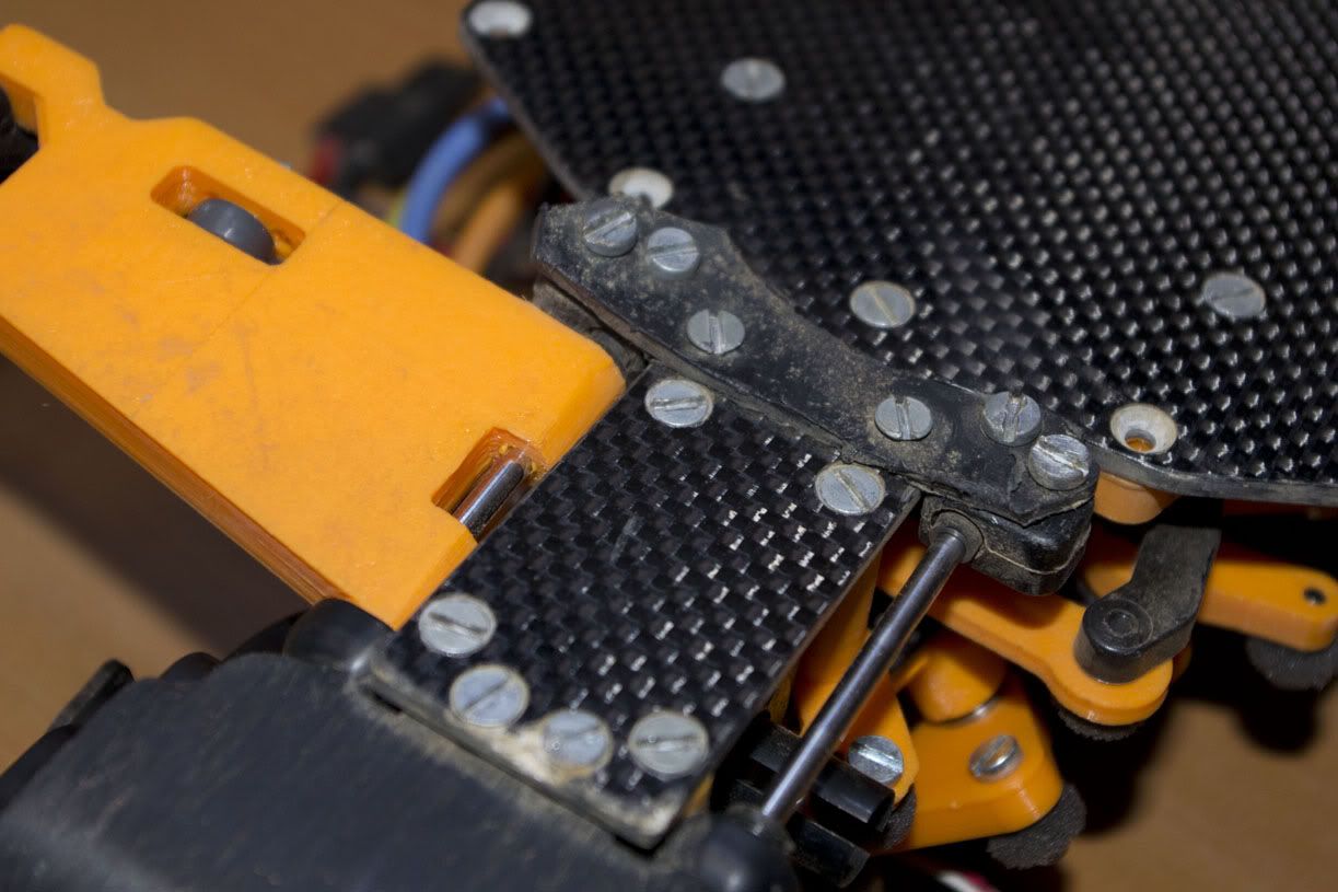 The first breakage of the day: the (temporary) plate that holds the rear suspension blocks for the front arms. It happened on the first jump when I tried to roll over it but went slightly too quick. The front end dropped about 20-30cm and it broke in half. Luckily some people helped me to do a trackside repair: a cut up piece of motor guard from one driver, a Dremel from another driver, a bit of creativity and I had it back up and running within an hour or so. This repair enabled me to run all the other laps with the FF the rest of the day... about 20 of them. 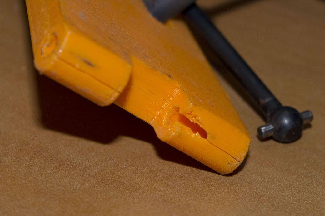 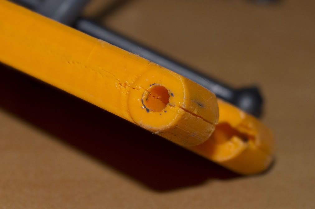 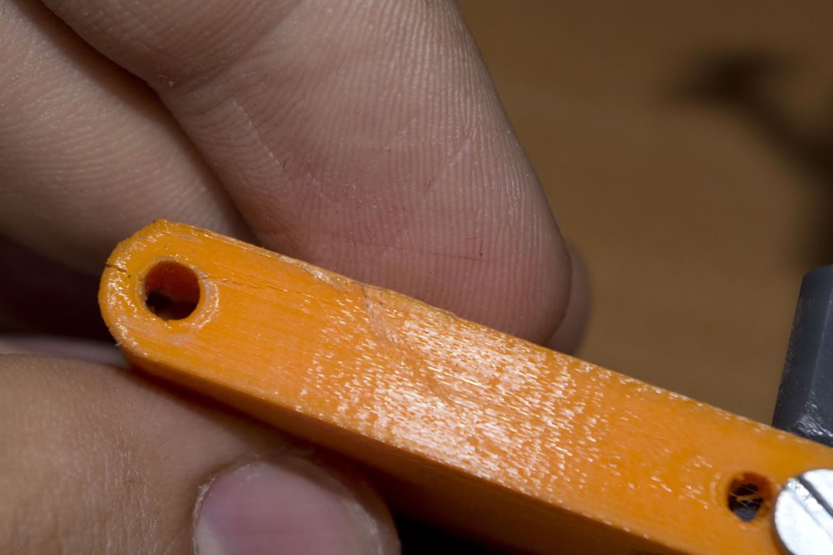 This is the broken suspension arm. It's a strange breakage: The suspension shaft is still on the car and it came off in a slight brush with a kerb. If you look closely it seems the part delaminated (cracking through a layer here and there switching to another layer). There is almost no material that broke away when the arm came off (and what broke off broke off in an odd place. The cracking probably happened on the bumps and the hops it made in those laps, making a crack. The brush against the kerb was enough to flex the material and pull the arm off the suspension shaft. There are carbon parts and stronger 3D print parts on the way so I can soon test it again, but I'd prefer to have something as a backup for the upcoming event, so if I can find time for it I'll also make some arms by hand from a plate of material (probably sacrificing a cutting board or something) 
|
|
#124
13-08-2012
|
||||
|
||||
|
Looks cool running and yes i did thinmk it was a bit light and bouncy at the rear end.
|
|
#126
14-08-2012
|
|||
|
|||
|
Yup, we just use them to create something to hand round in meetings and maybe do some fit and form testing. They never get run. Or at least, they don't get run for long (before they explode!!).
If you have the models you used, you can probably get one of the guys on here to machine a set up out of something more suitable. Or even go for a more complex shape to reduce weight/tune stiffness.
|
|
#127
14-08-2012
|
||||
|
||||
|
Quote:
Knowing that the part from this (vintage) car is known to fail quite easily (and therefor is quite rare), this part keeps the runners from ending up on the shelf or in an old box (because owners can't find the replacement parts). Coming from that and having seen how accurate and strong 3D printed parts can be (even if they are not nearly as strong as reinforced plastics), I put a lot of faith in them
|
|
#128
14-08-2012
|
||||
|
||||
|
How about making additional holes so you can place some zip-ties around the parts of your wishbones where the shafts are?
__________________
__________________________________________ Kyosho RB5 SP: RB5 Mid: ZX5 FS: Orion: Spektrum
|
|
#129
14-08-2012
|
|||
|
|||
|
Nice
. Some stronger parts and some work with your setup and you got a potentialy fast 2WD. With all that weight on the front i would have startet with the stiffest springs you can get your hands on in the front and the softest in the rear and go from there.
|
|
#130
14-08-2012
|
|||
|
|||
|
That's looking great....you've certainly achieved a lot there and filmed it!
I agree with a lot of the above comments..."a proper" proof of concept car is what's needed to take it to the next level i.e. with the stronger wishbones etc.. Obviously, try some better (i.e. less worn) rear tyres on your next trial..this may well help handling a bit alongside a change of spring/oil.
|
|
#131
15-08-2012
|
||||
|
||||
|
Thanks for the suggestions
I've contacted a member to get the parts machined (probably from Delrin). I'm also looking at an alternative to make is possible to produce the parts by laser cutting+drilling all the necessary holes afterwards with a bench drill. This method might enable me to produce suspension arms at the uni's workshop - if the laser cutter has enough power to cut through 8mm of polycarbonate - and if the employees there allow me to. They seem to be really strict about what materials should be machined/cut etc: They pretty much only let you cut Plexiglas and cardboard with the laser cutter - I guess it's time to push them to become more ambitious! Setup-wise, I've just ordered Losi Silver (3.4) and Losi Green (3.7) 2.5" springs (I used the 2.95 AE Red springs in the video) for the long/front dampers. As for the rear/short dampers, I think AE Silver (3.85) or AE Green (3.5) could work (I used 4.2 AE Blue springs in the video). Like I mentioned before, the oil will go up from #300 to #400 or #500. Note: All mentioned rates are lb/in. Someone also suggested a stabilizer for the rear - I think this might help to reduce the loss of wheel pressure on the inside front on power (thus meaning more forward traction)?  Also, it could prove interesting as a means to force a little oversteer on the rear. Also, it could prove interesting as a means to force a little oversteer on the rear. Which brings me to your point Naushad... The slick tires didn't seem to affect it's handling much on the first drive, even in the dusty conditions... but it's future 6.5T/5200kV motor (instead of 12T/3100kV) and some big changes in the damping and spring setup coming up, it may be a whole different story on rear slicks! I also think that when I start testing the car on astroturf, the rear bite will be more important to keep it stable.
|
|
#132
17-08-2012
|
||||
|
||||
|
As the first test run(s) have been made and I've worked on the car a bit I've now experienced the original design, and I've come with some updates for the car. I'll share with you the bigger changes to the car:
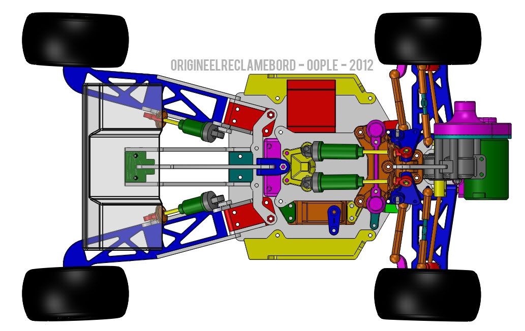 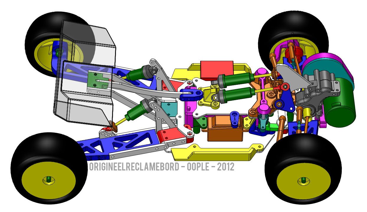 Most obvious probably is the holes in the suspension arms. This allows to increase the print fill without using more material: In short, the part is reinforced in the crucial areas. The sidepods are not really as much a revision as something I couldn't model until I knew the approximate width of the body that would go on the car. Keen eyes will also have spotted the following update:  On first glance it would affect the car in a bad way: higher CoG and weight balance further to the rear (and slightly outside). Upon the build of the V1.0 parts I came across a problem: the rear end had too much suspension movement when using the upper and lower middle holes. The only solution was to use the top hole on top and the rear of the three mounting holes on the suspension arm. I also found I needed a lot of spacing (some 5mm) to mount the damper to the rear of the three holes. The revised version solves these issues, as well as making sure the outermost settings are not used for what should become the basic setup of the car. (The image also shows extra material around the rear axle on the rear suspension arm and the text on the side instead of the top of the arm). Moving to the front end, I found that the outside wheel didn't seem to have enough steering compared to the inside one: the Ackermann angle was off. The image below is approximation of the old and new Ackermann geometry at approximately level suspension arms: 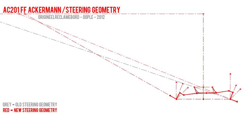 It's quite a difference Thanks to making the steering plate 10mm? wider (and putting the ball joints, which are the pivoting points of the steering plate, also 10mm further apart) the new geometry is reached. The inside wheel should still pull to the same angle, whilst the outside wheel on the new geometry is pushed to a bigger angle than before (some 5 degrees I think)? I think this should remove some of the understeer the car had, along with less tire wear and the ability to accelerate a little earlier out of the corners. It should also have a smaller turning radius (though I'm not sure how much use that is as long as the car can run on it's 'best' racing line).And last but not least, I did some improvements to make maintainance easier: 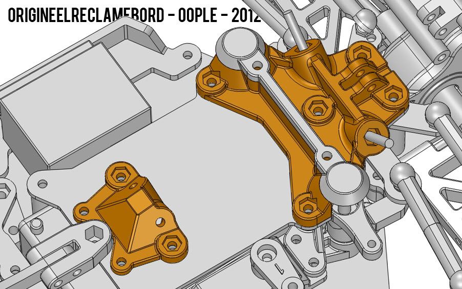 The rocker arm/steering frame was difficult to remove, making the whole top chassis time consuming to remove (which in term makes it an absolute pain to replace/setup/change anything on the front lower suspension or gearbox). Using some embossed pieces with hex shaped debosses in them, the strength of the original part is retained whilst also enabling me to undo the part just using a screwdriver. In addition to that, I decided to add more material around the rocker arm axles, as well as using large fillets to distribute stresses better. The frame that holds the top mounts of the dampers was also rather an unpractical part. It's still not optimal (removing it from the top chassis won't go very quickly, but at least now the dampers can actually be removed from the block without taking the whole top chassis plate off (It's not visible how I solved that on this picture, I'll add it later).That's all for now... I'm curious to see what effect the updates have to the track and trackside experience
|
|
#133
17-08-2012
|
|||
|
|||
|
Quote:
|
|
#134
17-08-2012
|
|||
|
|||
|
Quote:
|
|
#135
18-08-2012
|
|||
|
|||
|
Why have you pushed the gearbox output cup so far forward of the front wheels axle line?
The universal Joint used in rc cars will cause chatter when run at a angle. Due the of velocity sinusiodaly changing dependant on angle that the joint is bent at. See the maths here http://en.wikipedia.org/wiki/Universal_joint It a potential stress and vibration problem and means in a straight line the wheel velocity is contantly changing. Also the rear trailing arms are long are you putting track arm at the bottom of the rear wheel hub to control the side load? You may have an issue with the hingepin being subjected to a bending moment whinch fatigue the arm or snap the are and the hinged joint.
|
|
#136
18-08-2012
|
||||
|
||||
|
Good question - ideally the driveshafts should indeed be (almost) colinear from the top view.
The answer to the outdrives being so far forward has come from a lot of work and mockups with the steering, suspension and driveline. The thing is, if the driveshafts are in their 'ideal' position, the steering arms will be in the way of the suspension arms if I try to get a good ackermann angle - not to mention the gearbox is also kind of blocking the way for a compact steering system. I could put the steering arms higher up, but that's where the inboard suspension is at. The inboard suspension is used because there is a lack of space around the slipper clutch/camber links/steering links/driveshafts. And then there is the weight balance to consider as well. So at some point somewhere, you'll have to compromise. I know at full deflection these driveshafts don't rotate very smoothly, but so far on the pit table it seems the driveshafts are not deflecting to their full angle as they seem to rotate without clicking, binding and other grim sounds For now I've got a couple of things to sort out on the car: Basic setup on astroturf and clay, then to test it's capability to keep up with RWDs, and how well the car does in a race: How quick is it off the starting line? How quick is it compared to an RWD if you need to go off the FWDs racing line to defend or attack? Is it reliable enough? Are the trailing arms a problem if someone drives into you? Then once I get to know the car's character and basic performance, I can start looking for the areas to update and (attempt to) improve I think the driveshafts won't be the first on the list, but if it does seem to chatter it will be very important to look at (especially with the smooth power delivery this car demands).As for the trailing arms, I'm curious to see how it'll perform in the long term. The forces at play there will be considerable - it's something to have a good look at after every run to see if there is no damage or wear. Maybe it'll need 4mm hinge pins, who knows. If I can afford a weight balance that's further to the rear I could opt for a longer chassis, making more space for electronics in the process. Who knows what I'll end up with, for now though I just want to get a car reliable enough to last a race meet without breakage and get it around in a constant pace
|
|
#137
18-08-2012
|
||||
|
||||
|
Quote:
__________________
Visit my showroom
|
|
#138
19-08-2012
|
|||
|
|||
|
You may find that you need to design your own gearbox case which will reduce the design compromise.
I would try using solidworks simulation express an simulate the arms been subjected to a side load to see where stress concentration is on the arm and what load it will fail at. And then simulate it wit a fixed point benhind the wheel and see how much the stress in reduced and the max laod it will take. It would be better to use the professional simulation tools that SW provide as you and section the mesh and put differnt type of fixings in the simulation. P.S I would also put in all the fixings you are using, in the model. If you don't have SW toolbox use the mcmaster carr site they have all the screws nuts and bolts modeled up. I learnt the hard way in engineering why you need to put the fixings in assembly..... A reading list. You should also get your hands on a copy of Milliken's Race car vechicle Dynamics. Heinz Heisler books on advanced vehicle technolgy and a copy of the latest edition of the bosch automotive hand book. And the latest edition of the machinery handbook for a basic referance of engineering standards and calculations. Also get a copy of roark formulas for stress and strain.
|
|
#139
13-09-2012
|
||||
|
||||
|
Sorry for the radio silence in the last few weeks. The focus has been on school for the past two weeks or so, and it's hard to find time to work on the project.
I've got the new parts in from Jonathan - the embossed pieces make the car a lot easier and quicker to work on, and it seems the new steering plate works much better for the ackermann angle. I've also done some setup work: #500 oil (Tamiya) and Blue springs (AE) on the rear (in combination with the new shock tower/lower shock mounts) and #400 oil (Tamiya) and Red springs (AE) on the front. The car has much better damping already, though it seems the front needs more damping (also #500, or perhaps #600) - it may also need stiffer springs up front (but that's on tarmac anyway). The new steering plate does help at lower speeds, but at higher speeds (+on power) I still find it rolls too much and it has significant understeer - off power it is good - That means there's probably too much weight transfer? Edit: Good news!  I've finally got laser cut parts of decent looking accuracy and finish at school. Polycarbonate was a disaster (smoke, stench, burnt/black edges and the disapproval from the teachers at the workshop), but Delrin works a treat! It takes time, and the finish is not as good as PMMA/Plexiglas, but overall it looks really good! These parts after drilling the holes for the hinges should be enough to handle jumping punishment! I've finally got laser cut parts of decent looking accuracy and finish at school. Polycarbonate was a disaster (smoke, stench, burnt/black edges and the disapproval from the teachers at the workshop), but Delrin works a treat! It takes time, and the finish is not as good as PMMA/Plexiglas, but overall it looks really good! These parts after drilling the holes for the hinges should be enough to handle jumping punishment!
|
|
#140
28-09-2012
|
||||
|
||||
|
I'll continue my last post here... I've cut the suspension arms and rear suspension blocks with the laser cutter and drilled holes in them - Their finish isn't very neat and it's accuracy is not 100%, but I think it will be good enough being such a rough prototype.
If I can find the time then I'll be updating the spring+damping setup tonight, and if all goes well then I will be testing it tomorrow on clay. With the Delrin arms I should be able to try some jumping, though I think the rocker arm system will really be put through it's paces by that. So what can I say? I can't wait to give you guys an update early next week!
|
 |
|
|


 Linear Mode

