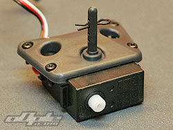
The steering servo is secured by a plate screwed down from above, similar to the arrangement in a Losi 2wd buggy (XXX, BK2 etc.) The top plate is secured with 4 screws into the main chassis, with these removed the top plate comes off with the servo attached by double sided tape.
The servo doesn’t have the usual tabs for securing but smaller tabs which slot into the chassis to hold the servo in place.
There didn’t appear to be a need for the servo plate to be taped to the actual servo but without the tape the servo can wobble slighty in its mounting so the double sided tape just takes up the slack and keeps the servo well held in place. I replaced the double sided tape with a section of “fluffy” Velcro, this presses down on the servo just as well but means it can be taken apart without having to peel tape off again. |
 |
 |
 |
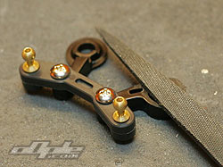
Servo plate is held in with 4 Phillips screws |
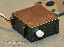
Servo plate with attached servo |
Servo, note the small tabs |
|
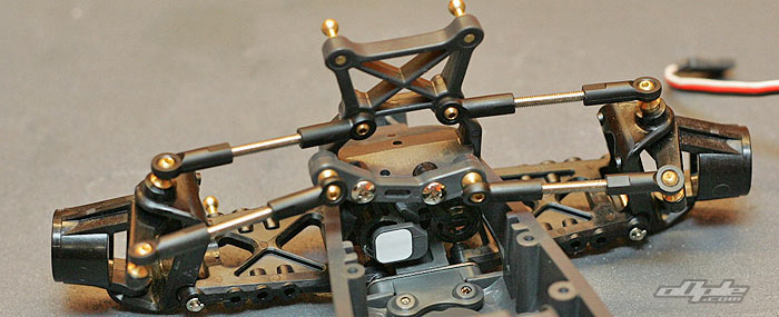
With the steering servo out of the car I noticed the steering was binding, which was probably the reason for some of the poor steering I experienced when running the car, so I decided to take the entire front end apart to have a closer look. 
The lower front kick up plate is separate from the main chassis and incorporates the bumper and hinge pin block. It’s secured with 5 screws (3 of which also secure the front shock tower). 2 of the screws however are under the inner hinge pins so the hinge pins need removing before you can disassemble any further.
|
 |
 |
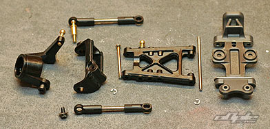 |
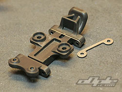
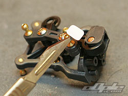
The steering uses a dual bell crank with one crank attached directly to the servo via a fairly nasty plastic servo saver (which has a sloppy action), and the other side to a separate moulding. This is the area where the main friction was coming so I disassembled it.
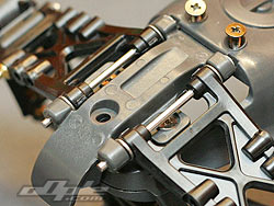
The bell crank pivots on a pin which is held in place by a small white square of tape, with the tape removed the pin falls out and crank can be removed.
I filed each side of the crank until it would rotate freely in the mount and replaced the pin and tape. |
 |
 |
Small sticker holds the pin in place |
Filing the bell crank to free it up. |
|
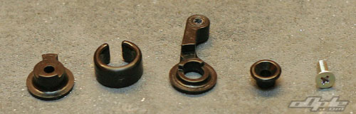 |
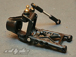
Servo saver assembly. |
|
The servo saver makes up part of the steering linkage so can't easily be replaced by a 3rd party item which is a shame since its not very good. If you manage to find a better metal geared servo that fits and / or dont mind hacking it up to fit, you could always glue the existing servo saver.
As it is, the servo saver has slop and is too weak for any sort of high traction surface. |
|
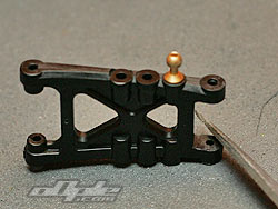
The tiny front suspension arms are quite fexible, like the rest of the plastic on the Frog, and should withstand some hard impacts, bending rather than snapping.
The outer hinge pin is held at the rear by a small E clip just like the inner hinge pins are.
Unlike the inner hinge pins however there is a small amount of friction here so the arm wont drop under its own weight when holding the hub carrier. The mating plastic surfaces touch slightly too much so I filed the inside faces of the suspension arms where the hub carrier sits. It just needed a small amount  taking off to make it perfect. taking off to make it perfect. |
 |
|