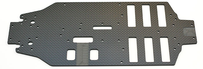
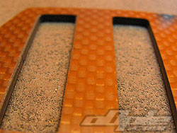
The main chassis is a class piece of carbon fibre with recessed areas around the motor and rear differential. Unlike the similarly laid out Yokomo and JConcepts buggys, the Tamiya doesn’t come with plastic trays for the cells to sit in (and to protect them). This means that the first step is to give these slots a slight bevel to take the sharp edge off, which otherwise might cut into the heatshrink of the cells and cause a short circuit.
This is not the first step in the manual but it is wise to do this before assembling anything onto the chassis which might hinder the job, or become scratched in the process.
The manual suggests to seal all edges of the chassis as well as the battery slots you just bevelled, using super glue. This is again a wise step as it helps prevent delaminating (splitting of the carbon layers) but I don’t often do it myself and have never had any problems. Having said that, it is an easy job and with a steady hand you can get a neat finish. I used a small off-cut of [tyre] inner foams dipped in the glue – and ran this along the edge very carefully to give a light coat.
With the chassis prepared it's time to get onto the first (!) step in the build.
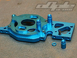
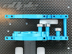
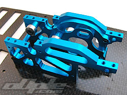
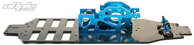
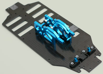
This first step is to install the lower steering mount and pivot pins, along with the centre bulkhead & motor mount. The manual is not clear as to which parts are where (again, no numbers on the bags). It is also unclear as to what material the parts are made from. I was looking for a blue aluminium steering mount but of course it had changed from the early prototypes and is now found on a plastic sprue “A”. |


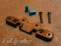
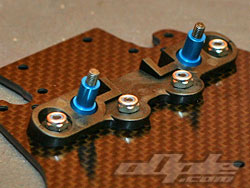
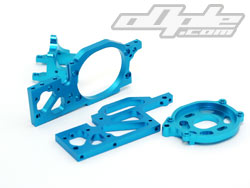
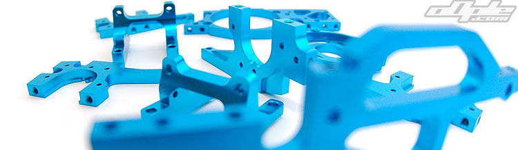
 All these parts (and plenty more throughout the 501X) are blue anodised aluminium and look fantastic. The blue is a deep colour and the machined parts have a quality satin look to them.