With the front (black) and rear (white) diffs complete and sat on the desk its time to look at creating a place to put them. The “gearboxes” on the 501X are built up from multiple parts of carbon fibre and anodised blue aluminium in a similar fashion to those on high end touring cars and, of course, the Yokomo BX. |
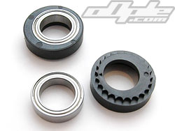
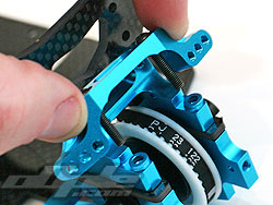
The differentials mount up in a similar way as seen in the Yokomo BX – with eccentric plastic sleeves around the differential ball races. These sleeves are notched and the notches key into a lug on either side of their respective differential housing. Lifting the differential upward slightly away from these lugs enables you to rotate the eccentric sleeves which in turn moves the differential – altering belt tension in the process.
 Small arrows moulded into the sides of the eccentric sleeves enable you to keep both left and right sides identical to one another. Small arrows moulded into the sides of the eccentric sleeves enable you to keep both left and right sides identical to one another.
|
 |
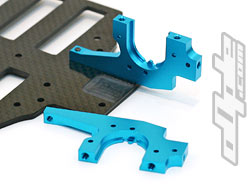  |
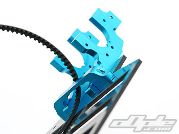
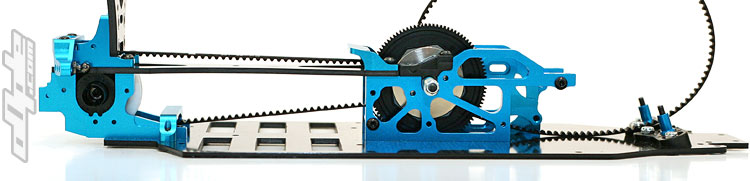
The rear end is first up and this consists of two large hunks of blue machined alloy which go to make up the sides of the gearbox. These screw onto the rear of the chassis and over hang a little way at the rear.
This overhang will go toward giving the rear of the car a little more clearance on rough tracks - in a similar way to that seen on the Yokomo BX, but this does away with the seperate chassis plate.
|
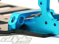
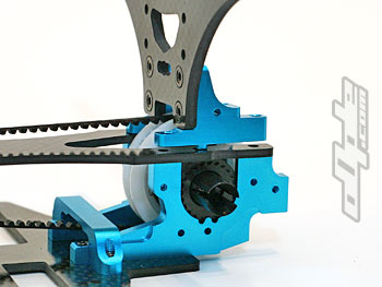
| The front-most suspension mount at the rear arches over the belt and both halves of the rear bulkhead before touching back down at the rear opposite side of the chassis. This is secured with two screws and has a ball style socket. |
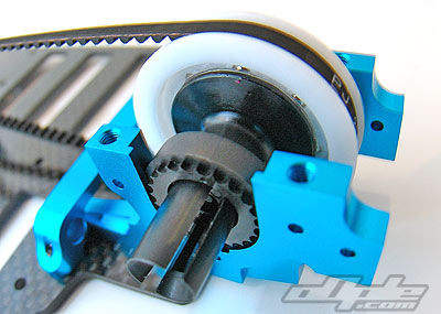 |
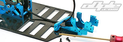
| The rear differential slots into the rear housing - to alter the belt tension, the differential needs to be lifted slightly and the eccentric sleeved rotated to the desired position. Small arrows (at the top in this photo) show the position at either side. |
|
 |
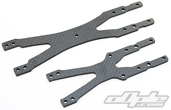
The rear top deck reaches from centre bulkhead to rear bulkhead and is cut in such a way that it makes it possible to remove without disturbing the differential position / belt tension - though the rear shocktower mount and camber link mount all sit atop this deck.
Eight screws clamp this rear assembly firmly together and anchor it to the centre bulkhead. Four screws push through a rather attractive aluminium stiffener with the Tamiya logo emblazoned across it.
The rear top deck is attached to the rear bulkhead through the rear shock tower / mount screws.
Right: Top decks, rear top deck at the top. |
 |
|
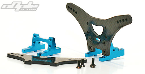
Both front and rear shock towers are of a similar design, being made from 3.5mm thick carbon fibre laminate with multiple shock mounting holes. These mount onto aluminium shock tower mounts which are in turn screwed down through front and rear top decks and into their respective bulkheads, front and rear.
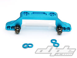
The inner camber link ball studs are mounted in a rather interesting and innovative way. Both left and right ball studs are screwed into a single aluminium mount which stretches across the rear bulkhead and down – placing the ball studs just above the differential out drives. |
This brace mounts vertically, so the inner camber link height (on both sides) can be raised or lowered in one step using the supplied spacer washers under the mount. The kit setting is two washers so that’s what I used.
Placing the washers precariously over the holes, whilst lowering the camber link mount with screws protruding - and trying not to knock them off into the gearbox, isn't overly fun. |
 |
 |
Camber link brace |
Installing camber brace over washers |
|
 An easier way to do this it just put a little grease on each washer, to keep them in place whilst you are installing the mount. These camber link mounts look very strong indeed, as does the entire car at this point. An easier way to do this it just put a little grease on each washer, to keep them in place whilst you are installing the mount. These camber link mounts look very strong indeed, as does the entire car at this point.
|
 |
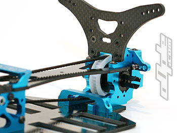 |
With the rear end screwed together its apparent how solidly constructed this car is. |
|
|