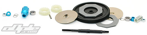
The slipper and layshaft are next and it is easy to see where this design came from – with obvious similarities to that of the Yokomo Bx again. The slipper parts are all Tamiyas own but clearly derived from those of the Associated RC10B4 (and used on the Yokomo BX). |
 |
 |
 |
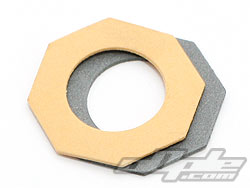
Yellow B4 pad on top of 501X pad |
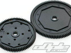
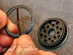
Small 78t B4 spur and 501X 96t spur |
|
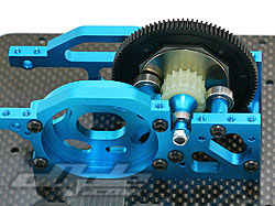
The actual spur gear is a large 96 tooth 48dp item (real 48dp this time) and uses ‘B4’ sized and shaped slipper pads made from a dark material with a similar feel to the latest white pads from associated. These are interchangeable with those from the B4 / BX so spares are even easier to find. The same goes for the spur gear, but getting a B4 spur at this large size might not be possible.
The rest of the parts are unique so it is not possible to use B4 slipper plates for example. |
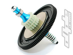
The lay shaft its self is a black steel shaft, to which you assemble the front and rear pulleys on one side and slipper / spur combo on the other.
 The pulleys sit over a blue anodised alloy sleeve and key into grooves around its circumference. The pulleys capture a pin that runs through this sleeve and into the lay shaft – holding the pulleys fixed to the shaft. The pulleys sit over a blue anodised alloy sleeve and key into grooves around its circumference. The pulleys capture a pin that runs through this sleeve and into the lay shaft – holding the pulleys fixed to the shaft. |
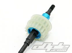 |
There is no centre one-way like on the Yokomo car, but it does look like one might be available at a later date. Or at least it looks possible.
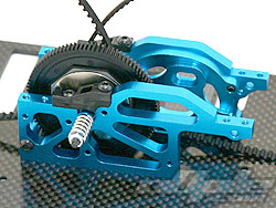
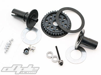
The dual pad slipper assembles next and the slipper plates lock onto flats on the shaft and a spring clamps the whole lot together – adjusted with a small nyloc nut. Varying this pressure adjusts the amount of torque that can be applied before slip occurs. |
 |
|
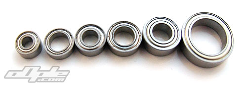
With the slipper complete the unit should drop straight into the alloy centre bulkhead. I say “should” because of course mine didn’t. After a bit of head scratching I realised that I’d used the wrong bearings on the belt rollers – it should be the bearings with a gold shield on one side, which are slightly slimmer.
With six different sized bearings and many being close in size, it can be quite tricky to pick the correct one – especially when you want to get the car done and on the track. This confusion doesn’t end at the bearings however – even the shims used in on the 501X come in three different sizes, the three bags are helpfully labled 0.2mm (thick) – Joy. Just something to look out for and you should be ok. |
|
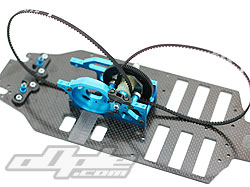
The belts wrap around the assembled lay shaft and these are identical front and rear. Once looped around their respective pulleys the lay shaft assembly can be installed. It is a little tricky to locate the belts on their appropriate rollers. Plastic clamps are used to press down on the bearings and keep the lay shaft in place.
The belts, at 4mm are not tiny, but are narrower than those seen on the Yokomo BX car. The Yokomo's belts were changed from the earlier prototypes for the final wide heavy duty type just prior to the cars release, being 5mm front and 6mm rear. Time will tell how the 501X's belts hold up to hard usage but the slipper should help. |
 The 501X uses ball differentials, and these are almost identical front and rear – the only difference being the size and colour of pulley used. While the rear uses a white 36 tooth pulley from the TA05 touring car, the front uses a black 35 tooth pulley from the TRF 415 touring car. The 501X uses ball differentials, and these are almost identical front and rear – the only difference being the size and colour of pulley used. While the rear uses a white 36 tooth pulley from the TA05 touring car, the front uses a black 35 tooth pulley from the TRF 415 touring car.
The smaller front pulley gives the car what is known as 'overdrive' on the front end, meaning the front wheels will turn slightly quicker than the rear – pulling the car around corners more and giving an overall increase in on-power steering. The side effect is slightly less off-power steering (corner entry).
It’s a shame there isn’t a choice here to have an even split (same sized pulleys front and rear). Pulleys should be available easily enough, should you want to swap to a 50/50 power split. |
 |
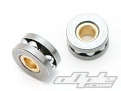 |
Differential thrust races |
|
The differentials are fairly typical of those found on many cars - there are only so many ways to make a nice differential. The differential halves are unequal lengths to offset the pulley to one side and the other (back vs front).
Small 2mm diameter screws are used to clamp the assembled differentials together – these initially did look undersized to me, and are the smallest I have ever seen on a differential. I am informed they should hold up to the job however.
The thrust bearings used are pre-assembled thrust race type. This is easier to install than the flat washers and loose balls found on most other kits, and is a welcome inclusion. One tip given to me is to install the thrust bearing so the side which is slightly recessed is facing the outside. This should let the screw sit flat on the thrust washer plate rather than the bushing in the middle – possibly spreading the load a little and reducing chances of a failure. |
 |
 |
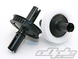 |
Diff pulleys |
A dab of grease keeps the rings in place |
Completed front and rear diffs |
|
 Left: The front pulley requires one flange attaching Left: The front pulley requires one flange attaching
Once together both differentials feel very nice and smooth. It felt like only minimal pressure was needed on the diff screw to tighten the diffs up sufficiently to keep them from slipping – there seems to be a greater range of adjustment here than most differentials I have used.
The manual would have you complete one differential at a time, with the rear gearbox build in between. But when you are building two virtually identical differentials it seems a little silly to split the builds apart. |
|