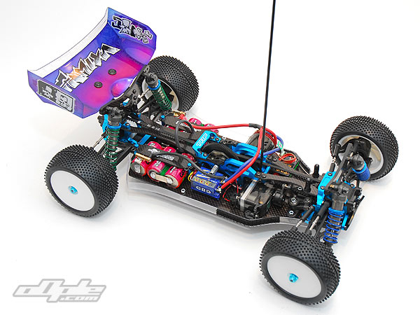
The electrics need careful placement in the fairly tight 501X chassis – don't get me wrong, there is room for  most things in here, but only with proper consideration. The routing of the wires to clear the various belts, layshaft and spur gear, access to motor screws, clearance of the low slung body shell - and other things need considering. most things in here, but only with proper consideration. The routing of the wires to clear the various belts, layshaft and spur gear, access to motor screws, clearance of the low slung body shell - and other things need considering. |
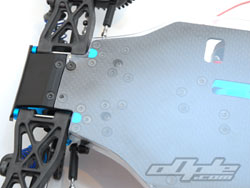
The first thing to install is the receiver mount – this is a rather obnoxious little mount which screws down to the main chassis, right under the centre bulkhead. This is then hidden from view by the servo which butts up against it.
This means that you need to thread the aerial wire through the mount prior to even deciding its (receivers) final location – and it is practially impossible to remove the receiver and swap in another quickly, or to swap between your different cars if you only have limited resources. It’s fine if you have many receivers and can dedicate one to permanent ‘501X’ duty – but I for one, do not.
Indeed, you later realise that if you install the under tray as per instructions, with double sided tape – it is an even worse task. If you install the under tray with screws like I did, then you are looking at 10 screws to install a receiver. I despise this mount - you'd do well to buy an alloy 3rd party item before begining on this stage of the build, and locating it in a more sensible area. |
 |
 |
 |
| |
|
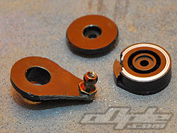
The steering servo is protected from damage by a Tamiya heavy duty servo saver on the actual servo horn. Different parts are provided to mate up to various brands of servo. Once assembled, the saver had noticeable slop – not much on the servo but once you get it on the car the effect at the wheels was amplified. The servo saver also felt a bit too weak to be effective on a high traction surface, so a fixed servo horn (not supplied) could be a better option if (and only if) you have a quality metal geared servo.
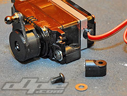
The servo mounts are small touring car style plastic affairs, which only reach as high as the lowest hole on the servo tabs. These felt secure, and with the kit servo saver should hold up well. My only concern with these was that the lack of support (only the lower holes and no bracing against the rest of the servo) could lead to a broken servo case in the event of a heavy impact. At least it could if you are using a stronger servo saver or fixed horn.
|
 |
 |
 |
 |
Blue Bird 617 MG + HS |
The "heavy duty" servo saver |
Small servo mounts dont give support |
I used one of the new Bluebird 617 MG+HS, high speed metal geared servos. This uses the Futaba style spline fitment and has a transit time of .09 seconds which is very respectable. |
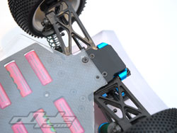
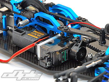
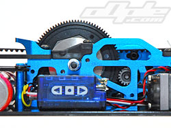
The manual suggests to install the ESC on the left of the chassis, behind the motor – and the receiver on the right. There are certainly a few options here, and the size of your electrics will likely influence your choices.
The smaller the better is a good guideline, but even the largest current electics can be fitted. |
|
I decided to run the ESC on the right, under the lay shaft. And the receiver over on the left in front of the motor. The receiver wires from ESC and Servo run under the plastic aerial mount (did I mention, I hate it) to keep them away from the belts.
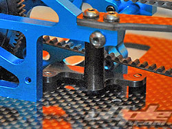
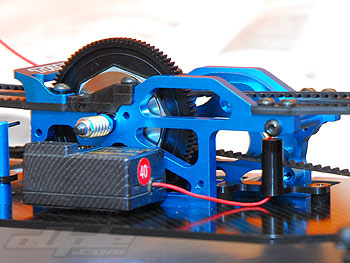
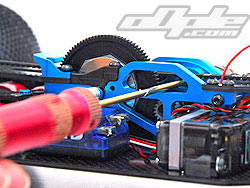
Motor installation is relatively straight forward, but the pinion really needs installing prior to fitting – then it can be adjusted for depth to match the spur gear. Tamiya supply a pinion gear to get you started (if you don’t have any, I guess), this is 48dp to match the spur, and 17tooth. The pinion needs to be quite far out near the end of the motor shaft – fine for the supplied pinion but some pinions might not be quite long enough to reach. |
 |
 |
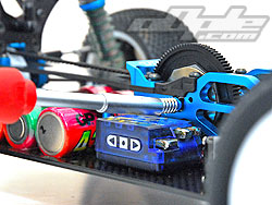 |
Just enough room for my esc! |
Motor access through the bulkhead |
Setting the slipper |
|
 |
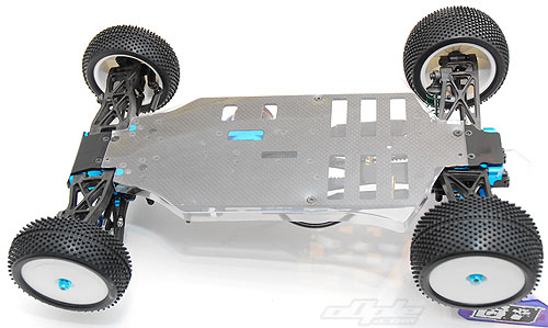
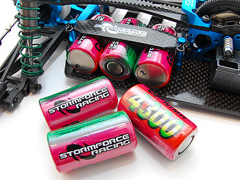
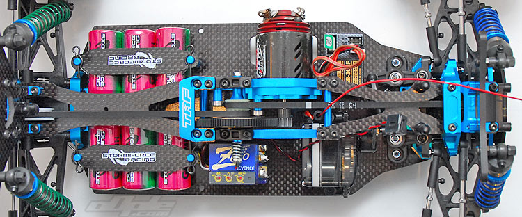
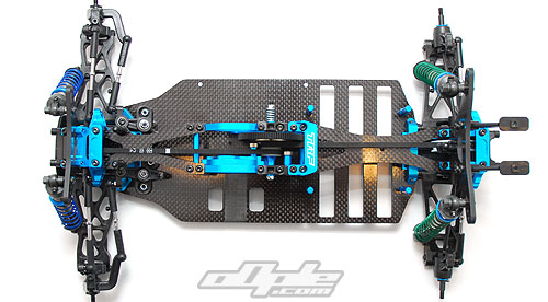
The cells sit in a saddle pack formation at the rear of the chassis. Unlike the increasingly popular plastic trays, these cells sit in the computer cut (and hopefully bevelled by you) slots. This is a slightly old skool way of doing things and isn’t really fitting for a car of this quality.
The cells need a link wire between two the two saddles, and this needs to reach up and over the rear top deck and clear the belt. Too long and it can move around and get caught on something / too short and it can be difficult to clear the belt. |
|
|
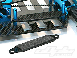
Four blue aluminium posts screw onto the chassis from below, and these hold carbon fibre battery straps secured with small body clips. The straps themselves are supplied with self adhesive foam to press more firmly on the cells and stop any movement.
The cells I am using are from a small company called StormForce Racing, based in the Midlands / UK. Neil at StormForce supplied some of his excellent and powerful matched GP4300 cells for the 501X review -and we thank him kindly for his support. The GP4300 cells are GP's current top of the line, and match the 501X in this regard. |
|
|


 can be thought of as VIP seating at a Metallica concert - mine are more "in the mosh pit" at a Slayer concert. No idea what I am ranting about? Then skip this part... quick :)