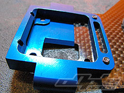
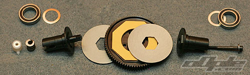
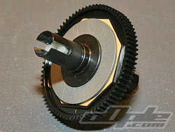
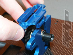
Previous - 1 - 2 - 3 - 4 - 5 - 6 - 7 - 8 - 9 - 10 - Next

Brief as bag A was, its onto bag B which contains a bevy of blue anodised alloy components.  All the parts are intricately machined and the quality of the anodising seems to be top notch.  I actually scratched away at one of the pieces with the metal file I used on the chassis and it took some scratching to get to bare metal. Nice.

Working front to back, the front bulkhead attaches with 2 screws to the main chassis, and has a recess already milled out for the gearbox to sit in.

The BJWorlds has a centrally mounted motor so the spur and slipper assembly is held in a neat alloy housing comprising front and rear alloy halves with an alloy bulkhead which ties the two together. 
The front part of this centre bulkhead doubles as the motor mount and keys into the motor cutout in the chassis for a firm base and is secured with three screws.

A neat carbon fibre bearing block attaches just behind the bulkhead with 2 screws and blue alloy nuts, this holds the lower steering ball races.

The rear suspension mounts (hingepin mounts) are the last part in this stage of the build.  These blocks come as a matched pair and work together to give the prescribed anti-squat and toe angles.  The blocks are cleverly machined so the pins run at angles through one block and then the other.  Naturally the measurements and machining need to be exact here and thankfully they are.

With the centre bulkheads attached to the chassis the slipper assembly needs putting together.  The manual says this is still “bag B” so I spent a couple of minutes looking for the slipper parts before finding them in their own little bag inside of bag C, ah well !.

The slipper uses the Spur from the RC10 B4, albeit in a 78 tooth version VS the B4's 81 teeth.  Accompanying yellow slipper pads from the B4 are used, these provide a good range of adjustment usually so should be alright here.  New versions of these pads in a white material will be replacing the yellow seen here from Associated.  The white pads have even better slip characteristics.
Assembled slipper
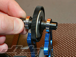
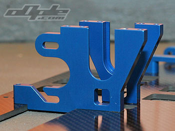
Slipper slides into the centre bulkhead
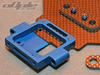
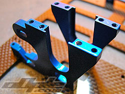
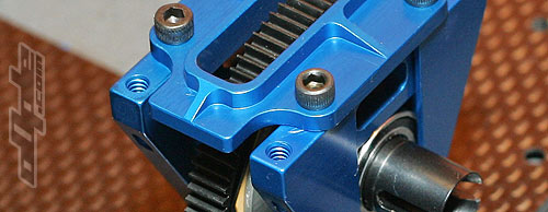
Top of centre bulkhead, holds bearings.

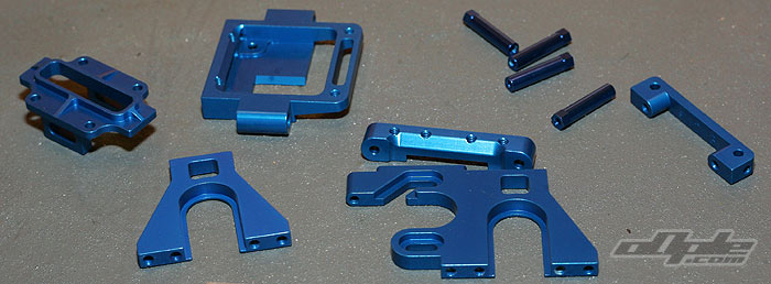
Building the slipper is like a cross between building a differential and building a slipper.  The spur gear and slipper pads are clamped from either side by large alloy discs.  These alloy discs key onto a hex on the  outdrives which take power to front and rear.
 The whole lot is clamped together by a long screw and diff nut, a spring is used to modulate the pressure applied and provide a range of slipper settings.

Putting the slipper together is a bit of a juggling act with the slipper pads jumping out of their position in the spur, slipper plates falling off the hex on the out drives and of course that goes for both sides of the slipper unit.  Once I wrestled the unit together it was ok.
I noticed one of the slipper plates wouldn’t sit flat on the outdrive, I mistook this for a manufacturing fault on the out drive but it turned out to be some sort of hardened grease or similar, once cleaned up everything was fine.
 
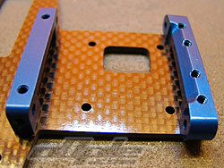
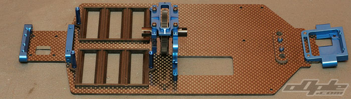
A thin metal shim washer goes over each outdrive on the slipper unit, followed by a rubber shielded bearing.  This then slides into the bulkhead on the chassis as the last part of the bulkhead screws down from above, pressing the slipper bearings into place and making everything very sturdy.

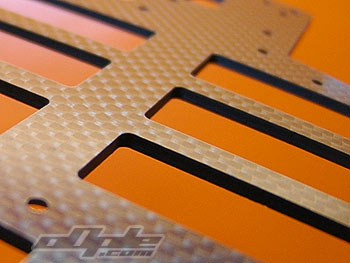
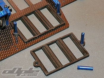
A hole cut into the chassis gives the spur gear some breathing room, it extends slightly into the hole which also gives an outlet to any small stones or dirt which could otherwise get trapped between spur and chassis, causing damage.
The spur is still a couple of mm from the bottom of the chassis, so even when running no undertray the spur should be safe from damage.

The chassis is slotted for 6 cells at the rear in a saddle pack formation - either side of the rear drive shaft. Unlike the original BJ4x4 however the the Worlds Edition requires no filing of the cell slots since the cells sit inside plastic trays which push firmly into the chassis slots.
Blue anodised alloy battery posts sit on top of the battery trays and when screwed in place from below make the trays immovable.
The cells are supported well in the deep battery trays which should mean you’ll never lose your cells in this car.
The cells are held in place finally by carbon fibre battery straps, these sit over the alloy posts and are clamped down by screws rather than body clips.  This should eliminate any possibility of the cells moving in a heavy crash, but it could also become a pain to have to unscrew the batterys.
I’ll reserve judgement on this until I have used it in anger.

Previous - 1 - 2 - 3 - 4 - 5 - 6 - 7 - 8 - 9 - 10 - Next