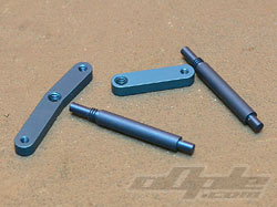
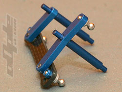
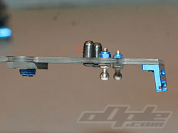
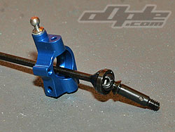
The steering is a fairly similar design to the previous car as there is no servo saver, just two anodised alloy posts which the bell cranks screw on to. A carbon fibre steering rack ties the two bellcranks together and the entire assembly pivots on small ballraces which locate in carbon fibre bearing blocks attached to the lower chassis and top deck. |
 |
 |
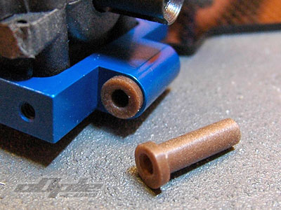
Steering posts |
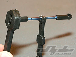
Finished steering assembly |
|
The bellcranks need thread locking onto the posts. From experience of the previous car I’d advise you to use liberal amounts of thread lock.
I gripped the posts using pliers and a paper towel so I didn’t scratch the posts, and just nipped the bellcranks tight to the posts - to make sure they weren’t going to move. |

 |
 |
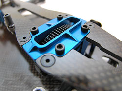 |
Front top deck with blue shock mount |
Completed front top deck |
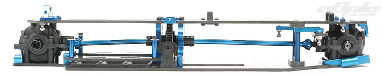
Centre bulkhead |
The inner camber ball studs are mounted under the top deck in one of two available positions, these are vertical and secured with a nut from above. The kit setting is the outer hole of two.
Included small plastic body mounts which are secured from below are next, followed by an aerial mount screwed onto the side of the top deck. It’s secured with 2 small screws from above so that it can be removed without disassembling half the car, nice.
The rear top deck is much like the front with a blue anodised alloy shock tower mount on top, bolted on from below. Vertical ball studs are used - like at the front - but this time without any horizontal adjustment with just the one set of holes.
The top decks secure to the tops of the gearboxes and the centre bulkhead, tying everything together nicely and creating a stiff chassis. With the front top deck mounted the steering was binding, I tried a few things to resolve this and managed to scratch one of the lovely posts in the process. In the end it turned out to be the steering bearings in the top deck weren’t seated correctly. After properly seating the bearings with a firm tap, everything was spot on. |
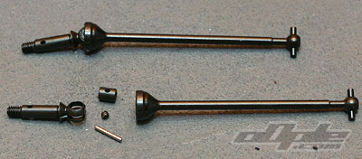 |
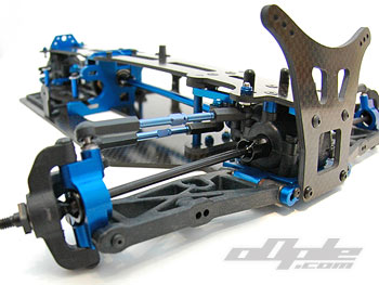
The drive shafts front and rear are MIP CVD units, specially made for the BJ4x4. The front bone is longer than the rear, with a corresponding short axle, and vice versa on the rear CVD, so both are near identical overall lengths.
These build up just like any other MIP CVD and like the centre CVD’s from earlier in the build. There was some material left inside all the holes on the bones however, meaning the small silver pin, which pivots inside those holes, was not free. |
| To solve this I ran my .05 driver inside the holes and just clear the burs out. This isn’t typical of these bones, I guess I just had a bad batch, either way running the car once would likely free them up. |
 |
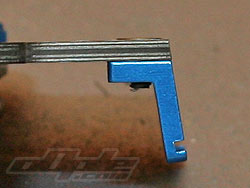
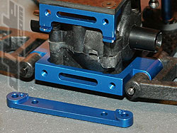
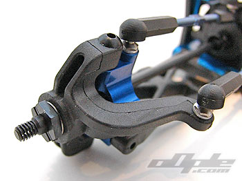
Front suspension mount - plastic inserts for hinge pins |
|
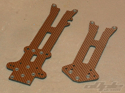
The front suspension is updated from the original BJ4x4, with the addition of the heavy duty front arms
and corresponding bulkhead. The rest, however, is the same, with Losi XX4 steering blocks and Jconcepts' own anodised alloy caster blocks.
The heavy duty suspension arms pivot on plastic sleeve inserts in the bulkhead. |
| These inserts are replaceable so you aren’t replacing the entire bulkhead when things get sloppy. |
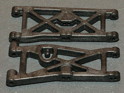 |
B4 arm above, Heavy Duty BJ4 bottom |
|
Unlike the previous BJ4x4 which used black plastic inserts which I found needed a hard push, these just fall in place.
With the arms mounted and hinge pins inserted through the bulkhead, there was quite a lot of slop evident, the arms can be rocked back and forth even more than my well worn B4. |
The front brace slips over the hinge pins and is screwed down along with the front shock tower, this takes almost all the slop away and the arms are left to drop easily under their own weight. |
 |
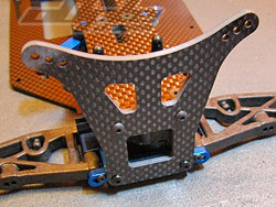 |
Front hinge pin brace |
Front shock tower |
|
The front shock tower is screwed on with 4 screws, 2 into the bulkhead and 2 into the front tower mount on the top deck. The tower is braced against the chassis well so should withstand front impacts quite well.
The assembled hubs mount to the suspension arms with a simple hingepin, and just like the inner hinge pins, it is captured by a small screw which just covers the end of the pin to stop it backing out, much nicer than using an E clip I think. |
It’s only slight, but the alloy caster block felt to have a little more back / forth movement in the suspension arm than I’d have imagined. No shims are used and I don’t have any small enough but it’s something to keep in mind. |
 |
Front CVD thru the alloy caster block. |
|
Team Associated blue anodised titanium turn buckles are provided, and are assembled with the standard Associated rod ends. All very familiar if you are own a B4 or other Associated vehicle.
I greased inside the rod ends before assembly to make adjustments easier later on. Plastic tools are provided for assembling the turnbuckles.
|
 |
Using the provided tools for turnbuckles |
|
|