 |
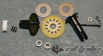
The front and rear differentials are next, and are identical front and rear. The differential ring gear is offset to one side in the TC3 gearboxes used in the BJ4WE, so the outdrives are unequal lengths as a consequence.
The outdrives come coated in oil and need degreasing first: I used some motor spray and a paper towel. |
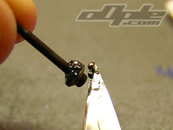
The thrust race consists of a pair of flat, hardened washers and six 5/64th sized balls, The thrust race is quite easy to build if you know how, the best way I found was to put a washer on the diff screw. Then using a scalpel, apply plenty of black grease. Using the same greased scalpel pick up one ball at a time (they should stick to the grease) and press them into the grease on the washer.
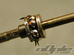
With all six balls in place, slide on the 2nd washer and insert into the diff half, the grease should spread around and over the second waster with a few spins of the diff. |
 |
 |
 |
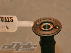 |
Preparing the thrust race |
Assembled thrust race |
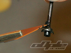
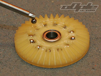
Dab of grease holds plates on |
With the thrust race assembled on the diff screw, it can be set aside until the rest of the diff is ready.
The diff rings sit over a shoulder on the inside of the outdrive / diff half. There is no locking of the two parts so the plate can spin on the diff half, though the clamping pressure of the diff screw should stop any spinning here.
A dab of silicone grease where the diff plate sits, stops them from falling off during assembly.
A spring and “T” nut are used to clamp the diffs together finally. |
 |
 |
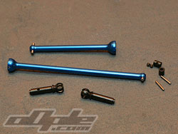 |
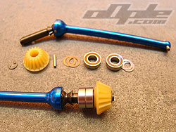
Centre CVD parts |
|
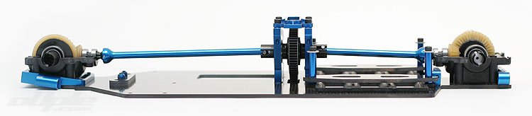
The drive from the centre to front and rear gearboxes is provided by blue anodised alloy CVD’s which have a drive pinion on what would be the axle end. The dogbone ends engage with the centre slipper outdrives later on. The centre CVD’s build up just like any other CVD’s and are identical apart from the overall length with the longer of the two going to the front gearbox and the shorter the rear.
|
 |
Front and rear centre CVD shafts |
|
 |
MIP Thread lock is included for assembling the CVD’s but is located later on in the build, along with the drive shafts.
The support bearings and drive pinions secure with an “E” clip at the end of the shaft, this is located in the shock bag which is explained in the manual, but its quite easy to miss and spend 5 minutes looking on the table. I wouldn’t be that silly though. |
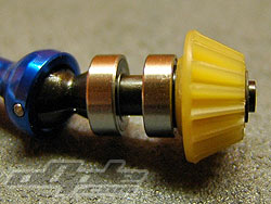 |
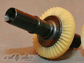
| I built the axle ends with the manual-suggested spacers, two thin washers per bearing. This provided a fairly tight mesh with the diff's gears'. Some people I have talked to suggested removal of one washer from the pinion side bearing because the bearings - when built as per instructions - would bind slightly. I left this area as per kit as it didn't seem too much of a problem. |
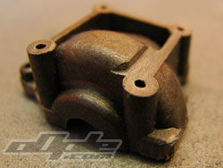
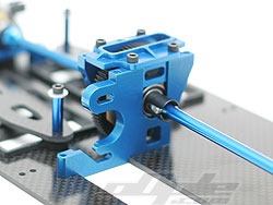
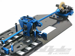
The gearbox housings in the BJ4WE are derived from the Associated TC3 touring chassis but are machined by JConcepts to fit better with their design - rather than compromise the design to fit the gearboxes. The front gearbox is most heavily machined since it now mounts on the sloping kick-up at the front rather than a flat touring car chassis. The work is good and everything sits nicely. |
 |
 |
Machined moulded front gearbox lower |
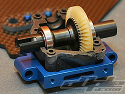
Lower diff case half bolted in |
|
 |
 |
 |
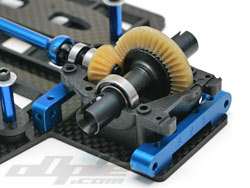
Rear gearbox innards |
A.C.D. - centre drive to front and rear. |
Looks lovely. |
The lower halves of the gearbox housings firstly screw onto the chassis with four screws each. With this done, the front and rear differentials drop in along with the CVD centre shafts / pinions. The gearbox tops finally screw on from above with 6 screws each finishing off the main drive line. |
|