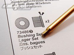
With a little experience it is fairly easy to learn the differences between different screw sizes - say, a 3x8 and a 3x10. The Hot Bodies manual sadly doesn't trust you enough to supply this information in the actual build steps - instead supplying a cryptic code number next to every single screw, which causes you to constantly refer to the scale key at the side to make sure you are using the correct item.

RIGHT: John had heard about the "Lager Set" but disappointment was evident on his face when he realised it had no alcohol content, only rubber - come on HB, sort yourselves out! |
 |
|
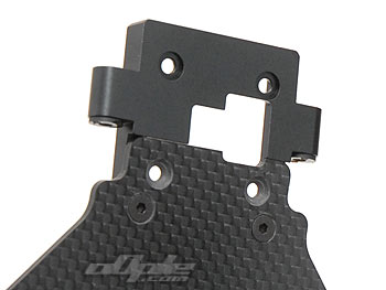
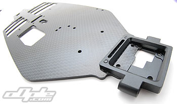
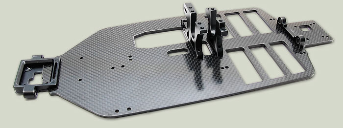
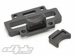
The alloy parts are all secured to the main chassis from below with counter sunk screws. The front pivot block sits right at the front, over hanging to provide the 'kick up' for the front suspension. |
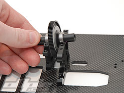
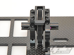
The centre bulkheads are attached in the middle of the chassis. The front most mount also holds the motor and there is a cut out for the motor to sit as low as possible here. Similar cut outs exist for the cells, front and rear gearbox and slipper to all sit as low as possible on the chassis. |
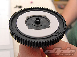
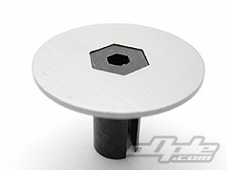
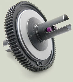
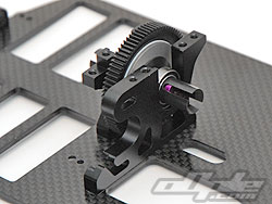
| The slipper is next - this is similar to other units around but uses bespoke pads and an 80 tooth 48dp spur gear. The pads are white in colour and have a similar look and feel to the newer pads from Associated - but these locate onto the spur differently, via four 'notches'. The two 'out drives' on the slipper are locked together by virtue of an interlocking hex, where one 'male' half locks into the other 'female' opposite - so once tightened the spur will slip between these two locked halves. If you've built a similar slipper then you'd probably already understand the fairly stright forward construction. |
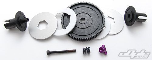 |
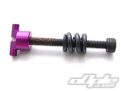
A 2.6mm x 25mm screw (try find one of those in a spares box!) threads through a spring, then the entire slipper assembly before screwing into an alloy 'T-Nut' on the other side. The alloy T-Nut has no sort of thread locking / nylon, so threadlock is needed to stop the whole lot coming apart mid-race.
The screw appears to already have some thread lock applied but we put some extra on to make sure. |
| Using a 2mm driver you're advised to tighten the screw all the way before backing off 1 and 1/4 turns to acheive a near perfect slipper setting. This is a mistake in the manual, or at least poor grammar, since this should read 1/4 not "1 1/4". |
Like some other cars I've recently built, the D4 manual suggests you install the steering servo at this point - crazy! Of course you can install it at the end of the build instead, so that's what we'll do as there's no point having wires trailing around just yet. |
|