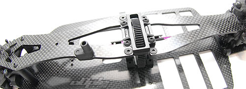
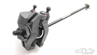
The power on all four corners is transmitted to the wheels via long steel 'CVD' style drive shafts. The actual joint is the opposite from the usual 'MIP' type - it's basically inverted but works in exactly the same way.
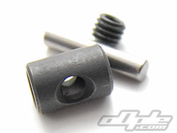
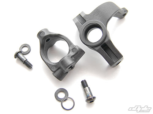
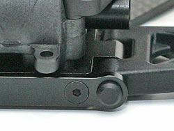
The pins are secured in the joint with a small grub screw - this is usually sufficient but after reading a japanese D4 blog, and later experiencing two drive shaft failures (one front and one rear centre) it seem to be a good idea to actually put a small flat on these pins to prevent them from backing out.
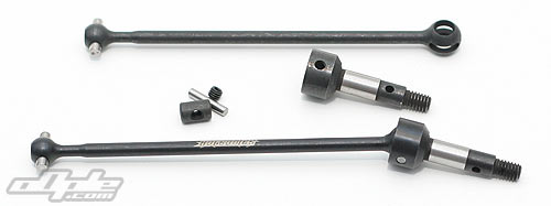
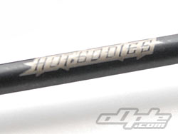
The manual seperates the front and rear drive shafts between stages - the rear coming a little later in the build manual. I thought it was a little odd to seperate the builds of these since they are identical in the construction - only the lengths of the shaft and axle differ. The front uses a long shaft and short axle, whilst the rear uses a short shaft and longer axle to give a fairly similar overall length.
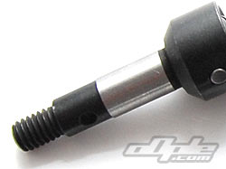
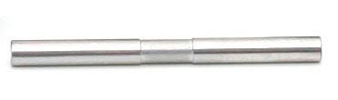
Since this is, for the most part, a Metric car - the car uses metric ballraces throughout. To give the best compatability with existing wheels (more on this later) the actual wheel mounting area is imperial, and 'steps up' to a slightly larger diameter which spins inside the bearings (the ground silver area on the  axles). axles).
|