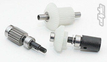
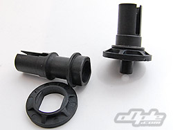
The differentials at both ends are ball type and of similar construction. The diff halves / out drives are similar lengths front and rear but the rear have an odd design which is half plastic where the diff rings sit.
This plastic part locks onto flats on the out drives and the metal diff rings are in turn keyed to flats on this plastic part.
The rings are supposed to be glued to the plastic diff ring holders, I guess this is because the stresses in the differential could eventually strip the plastic to which the diff plates are keyed.
I ignored this (I am stubborn) but after some advice from a friend who told me that the diff ring would slip and chew the plastic on the first run – I changed my mind and re-did this step with glue.
Since the front diff halves are the same as those on the rear, but of all-metal construction – they are a direct fit and much stronger. I can’t for the life of me understand the idea behind these 'half-plastic' items.
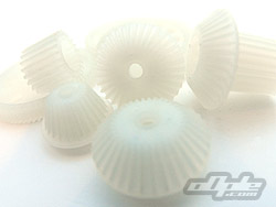
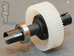
The rear diff gear is a white translucent item and looks like it should handle any abuse you can throw at it, with the wide teeth.
Ten diff balls push into corresponding holes in the diff gear and need a liberal coating of the supplied silicone diff grease. A pre-assembled thrust race is supplied which is a nice touch.
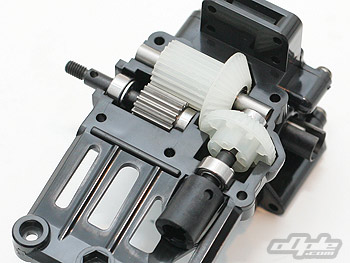
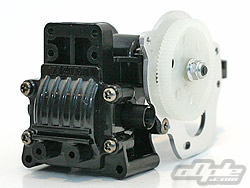
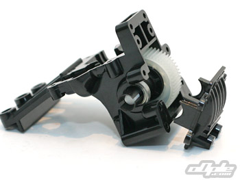
With the rear differential assembled the next step is to install it into the rear gearbox. This is a large & complex plastic housing which holds various gears and shafts.
The differential pushes in at the rear and a plastic cover seals things up with four screws - a nice touch which should make removal of the differential very easy indeed.
The gear box is moulded to arch over the motor and secure to the top of the main chassis' battery tunnel, and secures to the chassis at the rear from below. Moulded-in, non-adjustable suspension mounts are included - meaning antisquat cannot be changed.
The rear diff' simply slots in place, secured by the cover.
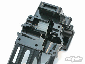
Seen from above
It is notable that the plastic isn’t to the standard of the TRF 501X car, but instead it's the same hard shiny plastic seen on cheaper Tamiya kits for many years. It's a little soft but that said, it isn’t the easiest thing to screw the supplied Phillips head self-tapping screws into – working on this car won’t be the nicest task in the world. A set of hex head screws would be a nice addition if you wanted to race the car (and fix it without blisters).
Three more gears need to be added to the rear gearbox – yes three! The rear gearbox is laid out similar to those seen on many modern two wheel drive buggys, with the main diff gear, idler gear and layshaft gear. The fourth gear picks up from the idler and sends it to the centre drive shaft.
Assembly of all these gears is fairly straight forward and is fully supported by ball bearings throughout. These gears drop in to the gearbox from above and a top cover is added to clamp the contents together.
It is advised in the manual to apply some grease to the gears – the only grease supplied being the differential grease.
This does add to the friction a little, and with all these gears the friction does add up so it’s best to either use a lighter grease (such as Tamiya Ceramic grease) or just use the silicone differential grease sparingly. Either way, the drivetrain should free-up over time.
All the gears in place - you can see the output shaft which takes power to the front gearbox
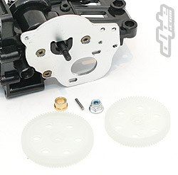
With the gearbox internals finished it’s time to look at the externals, and in particular the motor mount. This is thankfully an alloy plate which is secured to the gearbox with three counter sunk screws. I say thankfully because many Tamiya cars of this type have, over the years, featured plastic motor mounts – useless for anything but fairly tame motors.
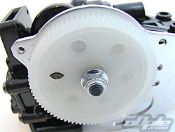
Two spur gears are supplied in the kit, a 78 & 85 tooth versions of the same design – the manual suggests using the 78 tooth version, but since I will be using fairly hot modified motors I went for the 85t. This gives an higher over all gear ratio, which is required for modified racing.
The spurs are both 0.5 Module – also sometimes called ‘metric 48 pitch’. The pitch is indeed very close to the common 48dp seen on many cars – similar but not perfect. This is a problem in that .5 Module pinions are few and far between so getting the correct ratio isn’t going to be easy.
48dp was first seen around 20 years ago from manufacturers like Team Losi – designed specifically for off road as an ideal intermediate between the larger 32dp and small & delicate 64dp.
Tamiyas own TRF 501X competition buggy comes with 48dp – so why doesn’t the Keen Hawk? Tamiya clearly know which is the real racing choice - 0.5 Module seems to be a misjudgement. You can run 48dp pinions with the 0.5 module spurs, but it sounds terrible and the life of the spur will be reduced.
The spur gear locks onto a pin though the lay shaft and a nyloc nut secures it in place. There is no slipper included in the kit. This is another oversight by Tamiya but one you can excuse because of the price of this car and the generally good spec.
An optional slipper is available and includes slipper-specific .5 module spurs. This is surely one of the best upgrades you can purchase for the car.
The manual would have you install the motor and gear cover at this point – but obviously there is little point since you can do this later, and it will get in the way of the photos!


 supported by ball bearings throughout. These gears drop in to the gearbox from above and a top cover is added to clamp the contents together.