With the dog bones in place and the camber links attached, the rear end is complete - for now at least. So it is time, finally, to have a look at the main chassis that this needs attaching to.
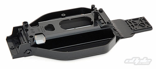
The chassis is a plastic tub – formed from the 'standard' Tamiya plastic you’d see on most of their non-competition cars. The bottom of the chassis bears a huge gaping chasm – to be filled later by the main drive battery and sealed with a large battery cover.
The chassis is noticably narrower than most other four-wheelers. The narrow layout of the main components has been utilised well by Tamiya and carried through to the whole chassis design.
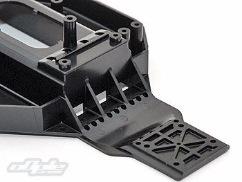
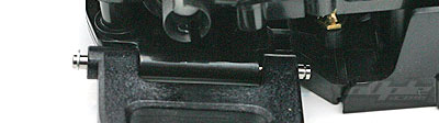
The front 'kick up' plate is added later but the rear of the chassis, which holds the gearbox, is moulded in place. The newly assembled rear gearbox screws directly onto the chassis from underneath and also onto the central battery tunnel from above. This gives a strong and secure location. The chassis is fairly flexible at this point but the battery and battery tray, among other components, will add some much needed stiffness.
Another striking factor is the tiny motor bay - there really is very little room between the rear of the battery compartment and the strengthening braces - and the rear gearbox.
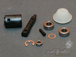
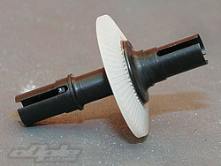
The front differential is, as already mentioned, very similar in construction to the rear – this time with proper (full metal) diff halves however, instead of the half-plastic items used in the rear. The differential gear used in the front is a crown wheel which faces out to the left hand side of the car and picks up the power from the centre drive shaft /pinion.
This pinion is installed along with a plastic drive cup on a steel shaft identical to the one used to draw power from the rear gearbox for the centre prop shaft. Three ballraces hold this front input shaft securely in position ensuring that the gear mesh won’t change with extreme stresses.
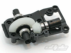
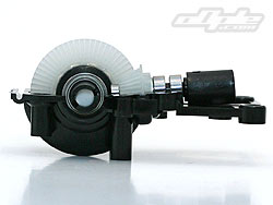
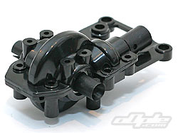
These two final gears sit inside the plastic front gearbox. There is no room to spare inside this moulding, with the outside gearbox closely following the profile of the gears. The gearbox has extra mouldings at the rear which act as a brace – attaching high up on the main chassis and providing additional strength.
A plastic top to the gearbox is secured with no less than six screws – half of them self-tapping and half machine screws, an odd and unexplained mix. The screws clamp the various bearings in place and prevent any possibility of misalignment.
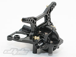
The plastic front shock tower mounts on to the top of this front gear box top-cover – sometimes this sort of design can be a weak point, putting pressure on the gearbox. But the DF03 gearbox is so well clamped together that there is little concern over any forces that may be transmitted from impacts.
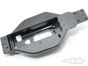
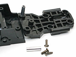
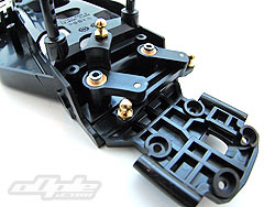
A plastic front nose plate is attached to the car before the gearbox can be installed. This provides some ‘kick up’ and has the hinge pin block integrated into it. The nose plate is attached with three screws from below, one self-tapping screw into the main chassis and two machine screws which insert into the twin steering posts - effectively sandwiching the nose plate against the chassis.
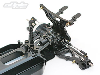
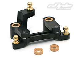
The steering on the increasingly crowded looking Keen Hawk is run of the mill ‘twin bell crank’ style. Once assembled, this slides over alloy posts installed over the nose plate.
The steering is the only part of this car which isn’t ball raced. Instead, bronze bushings are used – these do a good job but for smoother and longer life they can be replaced with ball races.
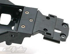
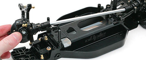
With the steering in place, the front gearbox and centre drive shaft can be dropped in place. The gearbox is secured to the nose plate and main chassis providing a nice strong mounting.
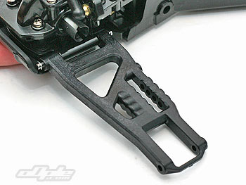
The front suspension arms pivot on the same long hinge pins as used on the rear. The manual shows an E-clip at either end of these hinge pins, but installing the rear most of these is tricky since there is very little room to work.
Reading a little further on in the manual, it’s clear to see that the front bumper captures these inner hinge pins anyway (stops them from falling out) – negating the need for any E-clips at all. I’d already installed one e-clip on each pin so left them as-is but without a clip at the rear as it isn’t needed.
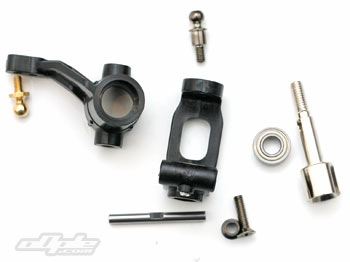
The front hub carriers are identical left and right, and like the hubs on the rear, these pivot on captured pins – so once more you have to break out the drill so you can install a grub screw.
The steering knuckles attach (with bearings and drive axles in place) to the hub carriers with a kingpin top and bottom. The top kingpin also acts as the camber link ball stud. The king pins can be tightened fully without any binding or notable slop in the movement – something even the mighty TRF 501X couldn’t manage.
Front hub components
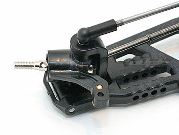
Assembled front hub.
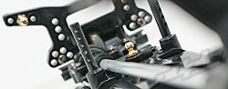
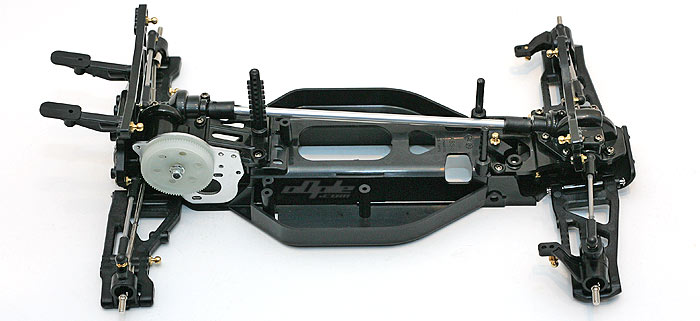
The mostly assembled chassis. Very neat looking if still a little flexible.