Previous - 1 - 2 - 3 - 4 - 5 - 6 - 7 - 8 - 9 - Next

With the diffs sorted the front suspension is attached to the car.  The manual assumed you have the bulkhead with wishbones and drive shafts etc all still together which in my case was partially true.
Threaded inserts from the XX4 are inserted into the chassis and the bulkhead is attached from below.  These areas have a lot more material around them than on the XX4 chassis to provide extra strength. 

The long yellow belt is, I am told, from the XXXs car.  This is fed through the chassis from the hole in the bottom and pulled through to the front. The front diff is placed in the car and the belt looped around it. 

The modified belt / steering tunnel is pushed into the space provided in the X-5 Chassis, this is a tight fit and needed a bit of a push until it seemed to snap into place, needless to say it’s a delicate part so be careful.
With the belt sitting over the hole I had carefully hacked out of the tunnel, its quite obviously too wide.  Ah well.

The already assembled steering from the XX4 is thread through the tunnel and positioned in the chassis.  The bearings for the steering are a loose fit in the chassis, the top belt cover will tie it all together but any movement of the chassis and the bearings fell out.

The front belt cover now needed cutting since I didn’t do it earlier.. I  placed the cover over the chassis and looking at one side decided where to put the hacksaw blade.  With the cut belt cover attached there was a tiny gap which really doesn’t bear thinking about.

With the cover on and the front shock tower bolted down the one way definitely wasn’t spinning freely.  I asked about and got pointed to a little tip on the Xfactory website (www.4wdrc.com) which showed how to get a much free’er running one way.
It felt from the binding that the bearings were getting side load, and the tip confirmed this. As well as the body of the One way being wider the bearings sit very slightly further apart by around 0.3mm so are getting pinched slightly by the shoulders which are meant to keep them in place.   I used a scalpel to just remove a sliver of material from this shoulder, on the main chassis, front belt cover and front bulkhead.
After this the one way spun perfectly freely, If you are running the Diff in the front then you can ignore all this as it should fit fine without any work. (Lesro in the UK and Xfactory now offer their own One Way which is a direct fit without ANY mods - fantastic!)

Belt cover before modification
Trimming the cover to fit the X5
Nice and neat.

With the front one way you really can’t use the front plastic Universal Joints from the XX4, the stress of the one way under power will break them quickly.  CVDs from the XXX4 or those made by MIP, along with the yet to be released Losi LCD drive shafts are the only items which can handle the torque of the one way.
Xfactory also recommend CVD drive shafts on the front when using the standard Diff unit in the front.  Why the need here and not on the XX4 ?  Well with the single belt there is no clicker (centre one way) so under heavy braking the front transmission takes a real pounding and the small diameter plastic yokes can, and I’m told do, snap.

I built my front end up with some MIP shiny CVD’s taken from a XXX4.  Xfactory provide instructions in the tips section of the manual about the one way, and suggest grinding the ends of the pins on the CVD’s so they fit through the out drive saver rings and in the event of a crash will hopefully stop the CVD’s tearing the out drive apart.


Onto the rear end, and the rear diff goes into the previously modified bearing blocks just like in the XX4.  The pulley runs very close to the blocks and can be forced to touch them but under normal circumstanced there wont be any problem as the belt should keep the pulley in the middle, it would be easy to take a thin shaving off the bearing block or the pulley but its not really needed.

The assembly is wrapped by the long drive belt before being slotted into the car and the rear diff cover is screws on top.
At this point I decided it was best to pre-tap all the chassis holes, the chassis is a really hard composite and could be easily stripped out if the threads are not cut properly.  You can use the gold coloured screw that comes with the XX4 for the same purpose but I just used a normal screw which happened to have deep and well defined looking threads on it. I used a little grease on the threads and made sure to keep the driver straight.

With the rear diff cover on I was able to rock the out drives up and down very slightly, it looked as though even with the cover clamped down it wasn’t pressing the bearing sleeve fully.  I put the gearbox top on some medium sand paper and just gave it 30 seconds of sanding on a flat surface just enough to lower the top slightly when fitted, holding the diff in properly securely.
Rear cover
Rear diff cover

With front and rear transmission parts installed, next comes the centre spur and slipper.
Xfactory use a similar system to the XXX4 with a very large 102 tooth 48dp machined delrin spur gear supporting 6 plastic “pucks” which are slightly wider than the spur gear its self, the pucks are clamped either side of the spur by alloy slipper plates, a spring forces the plates to clamp the pucks at varying pressure to loosen / tighten the slipper effect.

The first step is to put a pin through the lay shaft which then engages the pulley which transfers the power from the spur gear to the belt.
The manual suggests to be cautious here as the pin is loose and could fall out during installation.  Who are they kidding ?  the pin in my kit was tight and required tapping through with pliers.

The lay shaft slipper assembly has a bearing either side which locates into long U shaped slots in the top of the chassis.  The bearings need to be an exact distance apart so the unit is not too tight and not too loose.  2 washers, .005” and .013” are used to adjust the width to get the desired result.

Tapping the pin through the shaft.
Spur gear with slipper 'pucks' inserted
Assembled Lay Shaft / Slipper
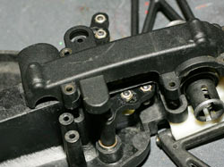
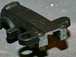
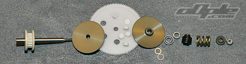
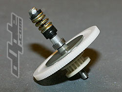
The slipper is easily adjusted with the nut, unlike the XXX4.

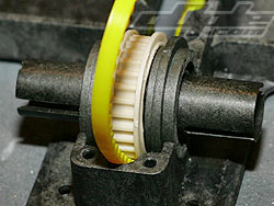
To get the spur to spin freely I ended up with both washers out and took of a small amount of material from the top hat washer to get it to fit in.

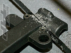
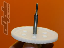
With the lay shaft now in the car and spinning freely, the pulley looked at first to be egg shaped, but on closer inspection the teeth in the middle looked quite good, just the flanges around the edge were quite out of ‘round’, no problem at all, but not perfect.

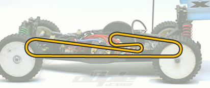
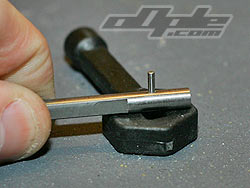
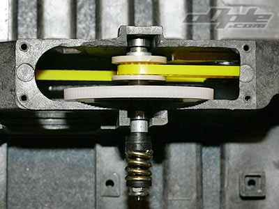
The belt is wrapped around the tensioner and lay shaft pulley, the tensioner then slides backwards to tighten the belt.  Xfactory advise the belt tension is the biggest factor in drive train performance, too tight and the car will be slow and put excessive strain on the motor, too loose and the belt will skip like crazy.
On the high grip tracks we sometimes run in the UK some belt skip under acceleration is inevitable and not a problem.

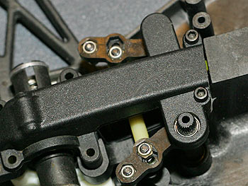
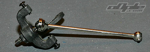
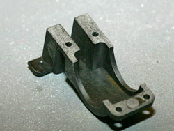
A moulded plastic cover  which extends up into the ‘drivers cockpit’ clamps the lay shaft in place and finishes off the drive train.

Illustration showing the route the belt takes.

Previous - 1 - 2 - 3 - 4 - 5 - 6 - 7 - 8 - 9 - Next