Previous - 1 - 2 - 3 - 4 - 5 - 6 - 7 - 8 - 9 - Next

The last modification required to XX4 parts is some small filing on the rear shock tower to fit over the new, higher, belt tunnel.

This basically just requires the front of the shock tower grinding away where it meets the top of the belt tunnel until it will sit flat on the pivot blocks and not rest on the actual belt tunnel / chassis. I used a dremel with sanding drum here but rounded file would work just as well. Either way it's best to keep the rounded corners at either side for strength rather than a sharp corner like you might get with a flat file.

Rear suspension is next, this can go on in one unit if you left it together from the XX4 strip down. With my out drive savers on the plastic diff, the pivot blocks were touching slightly, so I milled a recess off the top in the exact same fashion as the blocks in the latest XX4 Worlds Edition come prepared.

The pivot blocks and rear shock tower are located with the same four long screws, which first bolt the pivot blocks to the chassis followed by the tower, same as the XX4.
And just like on the XX4 this can cause problems because by the time the screw is tight with the pivot block, the tower can still need a few more turns to get it to sit flat.

One tip I recently picked up is to screw on the pivot block and carefully screw it down past the point of tight until it strips out the thread in the blocks, then it will be possible to screw the tower down fully with no loss of strength.
We broke 2 drivers assembling this area at a race meeting after a belt broke on the review XX4, stripping out the pivot blocks would have prevented this or at least reduced the risk.
 

I was always going to fit an Atomic Carbon rear brace, like on my XX4 but this wasn’t as straight forward as I’d imagined. 

The chassis on the X-5 is beefed up all round and is wider at the rear, fine for the floppy xx4 brace but the beefy Atomic Carbon brace overlapped the chassis.  I took a small amount of material off both rear corners of the chassis, this isn’t a critical area of strength at all so it’s no concern.


The almost complete chassis just waiting for shock absorbers before continuing..


With the bulk of the car complete its on to the finishing touches and electrics.
The steering servo is mounted upright as in the XX4 but this time lengthways along the belt tunnel.  The servo is a lot further forward than in the XX4 so a shorter Titanium link is provided to the twin bell cranks.
I found with the link screwed all the way into the ball ends to be too long, looking at the manual photos it also looked too long, I couldnt really understand this so just cut the turnbuckle down slightly at either end by a few mm so I could run the servo horn and bell crank horn paralell to one another

The cells as mentioned earlier are unique to the X5 being a 4+2 saddle pack. A long link wire is needed to stretch across the chassis. With careful placement of the connectors you should still be able to run the cells in a 2wd.

Forgive my tatty cells, feel free to send some in! *giggle*

I used corally style connectors and angled the tubes upwards to the front a little.

You can really see in the photo to the Right, how the cells and motor are in a block in the centre of the car, this is why the X5 has such good balance.

The cell straps on either side of the car are provided by Xfactory and are unique to the X-5.  The right hand side keeps hold of 4 cells and uses the body / cell posts from the XX4 donor car along with a long “X-5” Embossed plastic strap.
The posts lock into square holes in the chassis and are a tight fit, similarly the cell strap is tight over the posts and I used a reamer to bevel the holes slightly to make installation easier.
This cell strap has a large overhang toward the back which can be drilled for a transponder if desired.

The left side cell strap needs to be a compact unit as the cells sit very close to the motor, so Xfactory have used a length of rubber which is bolted to the chassis at the front (almost under the motor) and hooks over a post at the rear and is pinned in place.


This method seems like it works well and is one solution to the problem of securing the cells in a compact area.   In all honesty this rubber strap lets the car down a bit, it looks like it doesn't fit with the rest of the cars profesional finish.  The rubber is very hard to cut aparently and henceforth isn’t a super neat job, If Xfactory could use an automated process to cut the strap it could look a lot better, even better if it was black. It works, but its not pretty.

The motor attaches in a similar fashion to the XX4 (and XXX4) but does not use the lowered motor mount from the XX4 Worlds which is all I had, instead you have to use the standard item, luckily I was able to get hold of one (used) for the review.

Above: Left is the motor mount from the XX4 Worlds which not only lowers the motor but pushes it burther out because of the deeper profile and will not work. Right is the original motor mount.

Left: The motor is clamped from above by a plastic clamp which holds the motor tight.

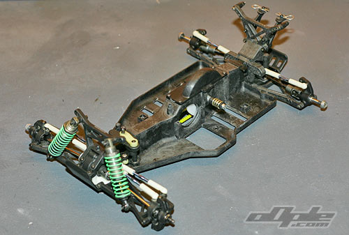
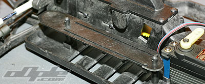
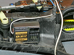
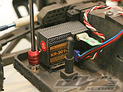
The receiver is designed to be mounted at the front of the car behind the steering and on the side of the belt tunnel.  There is a moulded ariel mount on the top of the belt tunnel.  The ariel wire is fed in the bottom of the mount (and into the belt tunnel) and then back up through the centre of the mount and out the top.  The bottom belt cover needs to be removed to do this, so if like me you regularly have to swap receivers between cars this could become a pain.


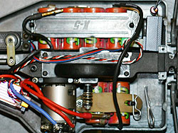
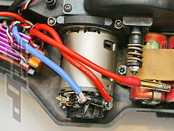
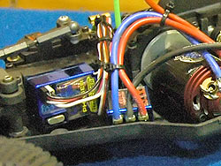
Dan Greenwood, XFactory team driver, uses a different method to mount his antenna / receiver. Dan mounts his receiver at the rear of the  X-5 on the right behind the cells and uses a 3rd party ariel mount which he has mounted to the chassis.  The motor / servo wires need to be run down the car but it does look a clean install. This leaves Dan plenty of room for his large Tekin esc.

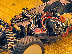
With the receiver installed as per instructions there really isn’t a lot of room for an ESC, I am using a small esc here, the Novak GTX which is a tight squeeze even before you take into account the large capacitor which needs to be housed.
The ESC that was in the XX4 donor car, an LRP IPC v7.1 is certainly too large to locate just about anywhere on the car unless you change the location of the receiver and mount the (large) Esc in the front.

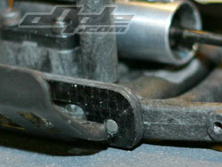
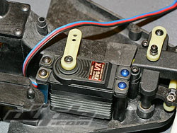
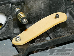
I first installed everything as per instructions but grew frustrated trying to locate the huge capacitor on the Novak and decided to use a similar lay out to Dan Greenwoods as previously mentioned. I drilled a hole and counter sank it with my shell reamer to mount the 3rd party alloy antenna mount, and put the servo behind the right hand cells.

Left and Right: The cars of two different drivers showing receiver / speed controller installs using the standard locations.

It would certainly be possible for me to have used the default positions but the method Dan Greenwood showed me looks a lot neater.

Previous - 1 - 2 - 3 - 4 - 5 - 6 - 7 - 8 - 9 - Next