|
The first part of the actual build is to install the electrics - eh! I skipped the Electronic Speed Controller (ESC) install because it would only get in the way for now and is just not necessary at this stage. The steering servo on the other hand does need to be fitted now since the chassis can, and in my case does, need some preparation to physically fit the servo.
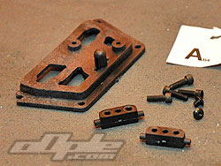
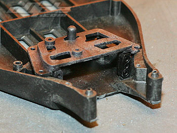
The servo is held in the car in a similar style to that seen on the Losi XXX series of buggys. |
| Instead of the usual servo posts which are screwed to the chassis from below, the X-6 uses servo posts with small ‘lugs’. These key into holes in the chassis below and into a top plate from above - which when screwed down, securely holds the servo. |
 |
|
This does seem a bit of a farce compared to the simpler setup on the B4 but does make for a secure fixing.
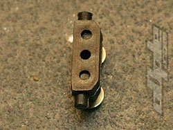
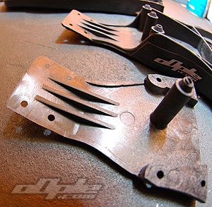
The servo posts are off-set to one side [see left]. This makes it possible to adjust the width of the posts to suit most servos just by turning the posts round and widening or narrowing the stance.
I also noticed the posts are off-set front to back, so can push the servo forward or back a small amount. There seems no reason you would ever run the posts so the lugs were further back since this would push the servo  forward slightly – and as you’ll see in the next step, this is just what you want to avoid. forward slightly – and as you’ll see in the next step, this is just what you want to avoid. |
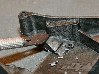
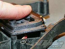
The chassis has a separate nose section and this bolts on just in front of the servo, the extra material around this area on the main chassis moulding is there to strengthen things in what could have been a potential weak point.
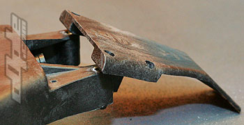
The problem with this extra material is that most servos will simply not sit down flat on the chassis, the front of the servos rest on top of this area slightly.
Obviously some servos might fit without any problems but for the rest of us a little work is required.
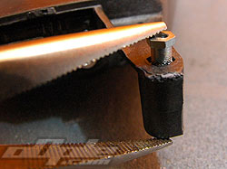
XFactory advise the use of a Dremel style tool to work away a little material at a time until the servo has enough clearance to sit flat. It’s a big assumption that everyone has a Dremel at home so I set about trying to disprove this need, by using a X-Acto scalpel type knife. |
 |
Servo riding high |
|
 |
This seemed ok for a couple of minutes, and it is fairly easy to remove matieral. But with constantly fitting the servo to see how much more needs taking off- it was clear that I would be there all day – or at least for a good while.
So, reluctantly I admitted defeat and broke out the Dremel along with a few choice cutting and sanding bits. I was quite surprised how much material I eventually I took off these areas, but from what I have been told there is no problem here even if you take significantly more off. According to XFactory this already has less material than the original chassis, and future mouldings will have even less. I think this can’t come soon enough since this step really shouldn’t be necessary. |
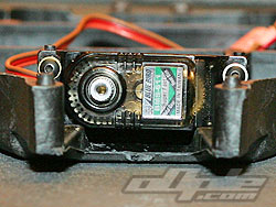
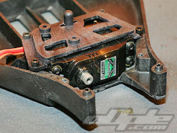
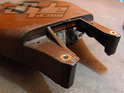
After a bit of work the servo was a good fit, so I attached the top plate and finished this part off. The top plate, as previously mentioned, is similar to that used on the LOSI 2wd XXX series buggies. This however is one of XFactorys own parts and for some reason has some of the ugliest holes I have ever seen. Cosmetics aside, the top plate does a great job of securing the servo and also comes with screws to attach a Personal Transponder, if you are lucky enough to own such a device.
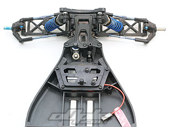
Since the cells on the X-6 sit a little further back than the donor B4, there is a decent amount of space behind the servo to hide excess wires and make a tidy electrics install. |
 |
 |
 |
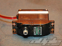
Bluebird servo, with servo mounts |
Ahhh, push it - push it real good |
Success! |
| XFactory would have you install the Receiver now, which would sit opposing the ESC on the right side of the chassis. Just like with the ESC, I did not want to put all the electrics in at this point so skipped the next few build steps and went on to bag B. |
Ā
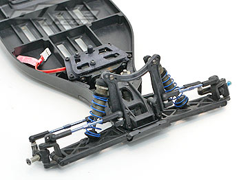
With my B4 front end refreshed with a new bulkhead and shock tower, I was ready to attach it to the X-6. Before you can do this however, the nose piece needs attaching to the main chassis.
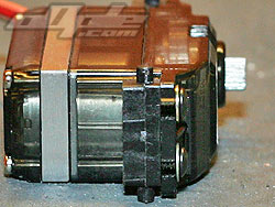
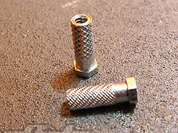
Firstly, threaded metal inserts are installed into the front of the main chassis from below, these are textured and require some force to push them all the way home. A few gentle taps from a pair of pliers did the job. |
|
|
 |
| Four screws attach the nose piece, two long screws from the conversion and two shorter ones from the B4 donor car. With this done, the ready-assembled complete front end from the B4 can be attached just as it was previously on the B4. The front end is done – hurray. |
 |
 |
 |
Threaded inserts |
little squeeze should do it |
Inserts should sit flush |
|