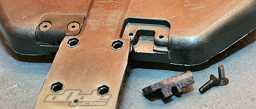
Inserting these `bottom covers` is the first job and each side locates from below with two counter sunk screws. The inserts follow the shape of the chassis perfectly but are of course replaceable should one become damaged – saving the racer from a potentially ruined chassis. |
Now it is time to concentrate on the rear of the car. The inner hinge pins locate front and rear just like on the B4. A plastic toe-in brace secures the rear, whilst the front of the pins is located inside plastic inserts – screwed into the main chassis.
|
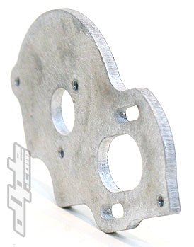 |
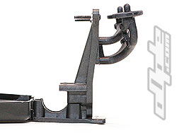
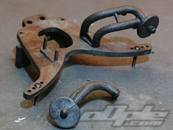
Thick motor plate braces onto chassis |
|
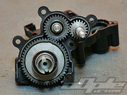
After cleaning up those old B4 gearbox internals – it’s time to build the X-6`s custom designed gearbox together.
The gearbox of the donor car would simply never do – just turning the B4's gearbox around to place the motor in front (like here on the X-6) would leave you with the motor driving the wheels backwards – not ideal!
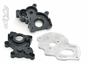 |
X-6 moulded gear case halves & thick motor plate |
|
|
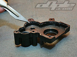
 With the B4 gearbox internals all safely pressed in place into the left hand casing, the right hand case needs preparing. To keep dust and grime from entering, a thin bead of grease needs to be placed With the B4 gearbox internals all safely pressed in place into the left hand casing, the right hand case needs preparing. To keep dust and grime from entering, a thin bead of grease needs to be placed  along the lip inside the right hand case. [see photo left] along the lip inside the right hand case. [see photo left] |
The actual fit of the two halves is quite good, possibly not as tight as that of the B4, but people often do the same on that gearbox so this is nothing of a design flaw – just a bit of advice from the X-team to provide maximum sealing. The case secures with two opposing screws at either side of the differential bulge. Three longer screws go right through both case halves and into the thick motor plate – securely clamping the assembly together.
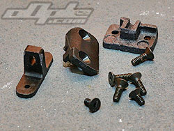
 The motor plate is, as just mentioned, thick – the front edge is screwed to a bracket attached to the chassis. This forms a part of the overall rigidity, helping to reduce flex. Four metal inserts are pushed into the bottom of the chassis from below. These will later be used to secure the transmission from above. The motor plate is, as just mentioned, thick – the front edge is screwed to a bracket attached to the chassis. This forms a part of the overall rigidity, helping to reduce flex. Four metal inserts are pushed into the bottom of the chassis from below. These will later be used to secure the transmission from above.
|
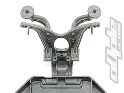
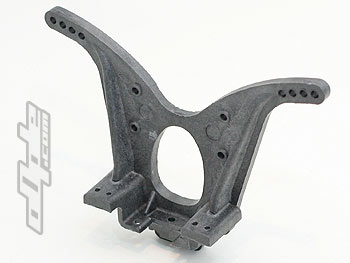
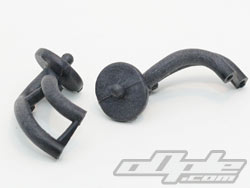
The rear shock tower is an interesting ‘swoopy’ affair with a large cut out section to aid airflow. The shock tower has the vertical camber link positions moulded-in.
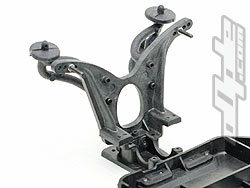
Large and intricately shaped wing mounts secure to the shock tower with two different length screws, 5/8” and ¾” long – this (imperial) probably makes sense to some people, but for the rest of us you just need to know that the longer of the two is used in the lower holes. |
|
|
The wing mounts seem quite stiff; stiffer than most for sure. This, along with the very wide stance, provides an excellent & stable base for the wing. It will have to remain to be seen how these stiff wing mounts hold up to some abuse – since this is a part I have broken on other brand cars several times. |
 |
 |
 |
Wing mounts provide a sturdy base |
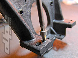
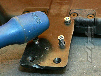
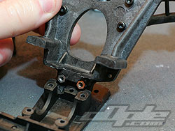
Shock mount screws need adding first |
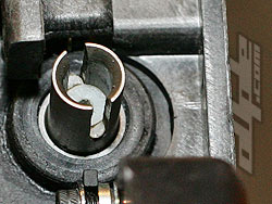
You can see the toe-brace inserts |
| Two small metal inserts push gently into the bottom of the rear shock tower and these will eventually hold the rear toe-in block.
The shock tower is lowered onto the rear gearbox – which sandwiches the metal inserts between the two halves. A single screw secures the shock tower for now but a further two screws, used to secure the transmission, also clamp the shock tower in place. |
|
This is where it the X-6’s transmission gets interesting. One thing is clear; Whilst the actual internals might be the same as the B4, some unique ideas have been incorporated into the design.
The most obvious of these is the height-adjustable transmission. This does what it says on the box; simply adding shims under the tabs on all four corners of the gearbox housing and optionally also under the motor plate bracket – you can raise or lower the transmission by various amounts determined by the 4 different height spacers included [giving five different heights including zero spacers]. Raising the transmission changes the angle of the CVD and alters the cars characteristic under acceleration and cornering.
It’s an extremely unique feature and one that most people might well avoid since it is new to them. The manual gives tips on how to go about inserting these spacers AFTER pushing the transmission into place.
The manual seemed to drift away from common sense here – unless I was missing something. |
 |
|
Suffice to say, the easiest way I found was to place all four spacers over their target holes [see photo above left] with the transmission out of the car– then carefully push the transmission in place and secure with all four screws, along with the small front bracket screw.
One thing you might notice, depending on the number or height of spacers used – is that the gearbox can have a small gap where it meets the chassis. The result is that you can see the diff gear and dust could enter here.
It seems slightly odd that the manual suggests sealing the gearbox with grease but then fails to mention this potential area for dirt ingress.

|
|
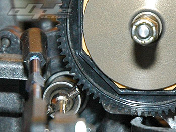 |
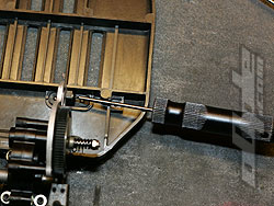
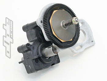
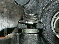
One thing that is pointed out in the rear of the manual after assembly, is the point that the B4 Kit supplied spur gear can have very little clearance from the differential outdrives and in particular the dogbone drive pins.
The X-6 manual actually suggests filing these pins down slightly so they do not protrude from the outdrives which would cut down the chances of contact with the spur gear. The alternative is to run a smaller 78tooth B4 spur gear (available seperately). This also has the effect of moving the motor back slightly - and is apparently what all the XFactory team use.
Though as can be seen from the photo, the spur is very close, in all my testing there never seemed to be an issue here - I did later move to a 78 tooth spur gear however, but this was more for the motor weight shift. |
|