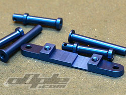
The first job is to install the battery and steering posts on the carbon fibre chassis, all deep blue anodised aluminium.
The steering posts sit atop an alloy mount which angles the steering posts back (at the same angle as the front kick up as can be seen later in the build, 10 degrees)
The mount for the posts is also recessed to allow clearance for the front drive belt.
 |
|
The main chassis of the BX, 3mm carbon with a nice semi-gloss surface. |
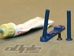
The four cell strap posts are next, all mount up with the same M3x8 counter sunk screws. Something I noticed right away was the ability to screw the parts on with light pressure and be able to really tighten everything down without the posts spinning around with the screw at all, I’m not sure why this is but it does make it a lot easier. I used Threadlock on all screws into the alloy just to be sure.
The last part of stage one is installing an aeriel mount on the chassis, this comes from a small plastic sprue which contains various servo mounting mouldings. The mount is a fairly familiar plastic piece with the vague possibility of being able to insert the ariel wire whilst installed, I’m sure its possible, just tricky. |
 |
 |
 |
Cell posts and steering mount. |
Threadlocking all the screws |
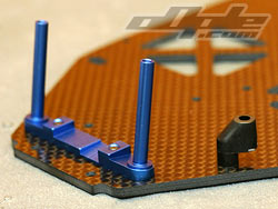
Assembled steering posts on chassis. |
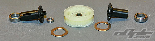
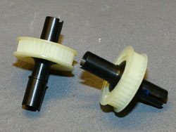
| The next stage of the build takes us away from our brief flirtation with the chassis and onto the front and rear differentials. Both ends of the car feature similar ball differentials. The rear differential pulley is in the centre of the car so the out drives are even lengths. The front belt is offset to the left of the car (as can be seen from the belt recess in the steering post mount, so the pulley is similarly offset with the left diff half shorter than the right diff half, both diffs are equal in dimensions when built. |
 |

|
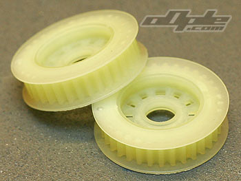
Identical pulleys front and rear. |
(front) Front outdrives (rear) Rear outdrives |
The pulleys are wider than just about any I have ever seen before on a 10th sale buggy and look to be high quality.
Metal shielded bearings are supplied and to my surprise appear to be lightly oiled and don’t require any work to free them up, which makes a nice change.
Each diff uses 12 main balls and 8 thrust balls, neither of which are ceramic, which is a shame as this is such a top level racer. The pulleys have ridges so you can just put all 12 balls on the pulley and you have a little puzzle game to get all the balls in the holes, once pushed in they are secured so cant fall out (unlike the X-5 pulleys which were not fun). |
Black grease for the thrust race and clear silicone grease for the main diff balls are supplied in little plastic screw lid pots, Yokomo are quite generous here and supply enough to do a few cars, the cynical might assume it is because Yokomo expect a lot of rebuilding, I think they are just kind. For the main diff balls I used enough to coat them well but not so much that it might get spun out by centrifugal force and get on the belts, that wouldn’t be good.
The diff rings have 2 flat spots for a positive location on the diff halves and to stop them slipping, I added a small dab of silicone grease to the diff halves which just creates enough adhesion with the diff rings to stop them falling off and making assembly difficult.
The thrust races are simply flat (hardened) washers with (8) tiny ball bearings sandwiched between. From my experience these tiny balls don’t hold up as well as the larger ones used in the Losi and AE kits. It would be nice to see a caged bearing unit used here to ease build (and maintenance, these tiny balls might get lost with specs of dirt on your pit towel trackside).
One extra of these thrust balls was included in my kit, not sure if that is on purpose because they are so easy to lose but as I was typing that last sentence a few got stuck to my arm and a 5 minute table top search ensued to locate the absconders.
Assembling the washers is fairly easy with practice, I put the first plate on the screw, then using a scalpel apply black grease to the washer, using the greased scalpel blade I can pick up one ball at a time and press it into the greased thrust washer. Once all 8 balls are in I simply slide the second washer onto the screw and running the assembled diff will do the job of spreading the grease over all surfaces.
The diff screws are slotted with a 2mm slot, this means you can use a (supplied) 2mm allen key / hex driver to screw the diff together, but it also means you can adjust the diff whilst the car is assembled without taking anything apart, you just poke a driver through the gap and spin the opposite wheel to loosen / tighten diff action, REALLY useful. |
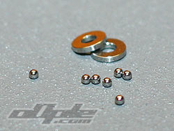 |
Flat washers and balls, thrust race. |
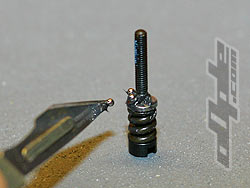 |
Putting the thrust race together. |
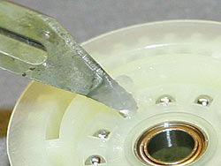 |
Applying silicone grease to the diff balls |
|
|
A coil spring is used to modulate pressure to get a good range of diff settings, I much prefer this to the conical washers used by some other manufacturers. The diffs differ in how they screw together, the front and rear have springs on opposite sides of the diff screw, the front screw goes into the actual opposite diff half which is threaded, where on the rear differential there is a special alloy insert used for the same purpose.
When assembling it appears the pulleys are designed to go one way round, they appear to be offset slightly with the smooth plain side having a deeper dish than the opposite side which has grooves moulded in. Just pay attention to the pictures in the manual and it should all be ok. |
|
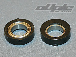
The belt tension in the car is adjusted by eccentric bearing housings on the diffs, these basically can be rotated into a number of preset positions, and the offset hole which carries the diff moves back and forth slightly to adjust tension.
These plastic housings have markings so you know which setting is in use, they must of course be the same left and right on the diff otherwise he diff could become twisted and throw the belt off.
The bearings are a reassuringly snug fit in the plastic housings.
With the differentials complete we move on to the slipper and layshaft assembly. |
 |
|