Previous - 1 - 2 - 3 - 4 - 5 - 6 - 7 - 8 - 9 - 10 - 11 - Next

The rear end gearbox is next. The rear end sits atop a separate 3mm carbon fibre plate from the main chassis, the whole rear end gets assembled onto this piece and later attached to the main chassis.
The sides of the gearbox, again blue machined alloy, are attached to the plate and the shock tower mount with belt looped around is joins the two halves and makes everything very stiff indeed.

The belts on the car as you may have noticed are seriously wide, 5mm front and 6mm rear and are equal in length. Earlier prototypes of the BX ran slimmer belts than this, the move was made for extra durability.


The rear belt is looped around the rear diff and the rear diff slots into the assembled housing.  The plastic eccentric bearing sleeves mentioned earlier have tabs which locate into one of 7 corresponding slots in the gearbox sides, it can be tricky to match these up on both sides as the diff needs to be lifted slightly to spin the eccentric sleeves.  I went with the kit suggested setting for starters.


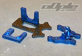
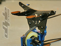
The rear shock tower needs assembly before attaching to the car, the wing mounts are identical to those from the BC Special and require a scalpel to remove a small lug around a screw hole so they will sit flat on the carbon fibre tower.
The tower its self is thick carbon fibre with two locations for the wing (low / high) and four shock mount holes. 
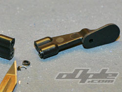
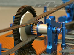
The shocks pivot on blue alloy bushings which are internally threaded and are screwed down to the tower with long screws.

The tower screws on to the assembled rear end with 4 screws.
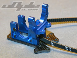
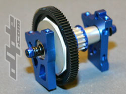
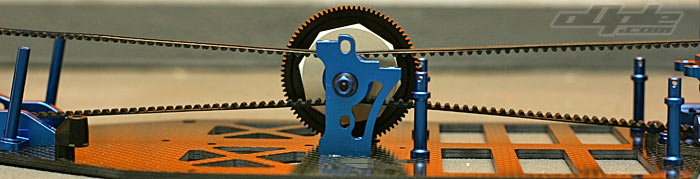
The inner camber link ball studs attach to a small plate which doubles as the gearbox top.  The ball studs have an external hex shoulder but also have an internal hex for a 2mm driver, with all the ball ends having corresponding holes in the top, this is usually a pro driver modification to aid in quick camber changes.

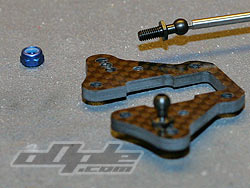
Rear camber plate, vertical ball studs.
camber plate secures rear diff in place.

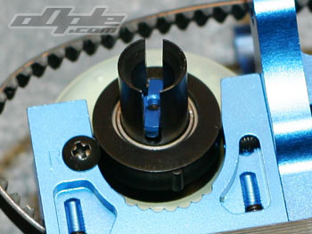
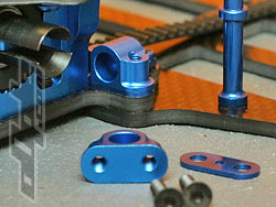
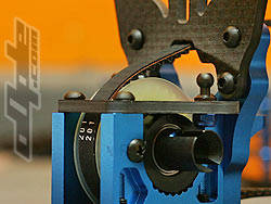
With the camber plate screwed down its time to attach the rear end of the car to the main chassis.  Two screws clamp the main chassis and rear plate together and then two screws each side go though both parts into the pivot blocks, these are small blue alloy parts with domed interiors.

The hinge pins for the rear arms pivot on large plastic balls which sit inside these mounts. Thin blue alloy shims are supplied to alter anti squat angles.

Wing mounts
Rear tower screwed on
Rear forward hinge pin holders.
It is noticable at this point that the rear gearbox / hinge pins are raised from the rest of the chassis by the 3mm thickness of the main chassis that it's bolted to. According to Masami Hirosaka from Yokomo, this aids in bumpy conditions because there is more clearance at the rear, even when the car is squatting down it is higher than it would normally be because of this raised rear section.

The finished layshaft unit from earlier is placed within two nicely machined blue alloy mounts and the front and rear belts looped around the pulleys.

The large 84t spur gear protrudes into a slot cut in the main chassis.


Previous - 1 - 2 - 3 - 4 - 5 - 6 - 7 - 8 - 9 - 10 - 11 - Next