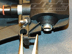
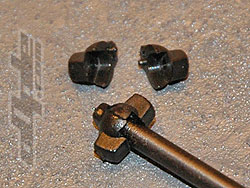
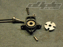
Drive shafts on all four corners are the same overall length but the front has shorter axels and longer shafts and vice versa, and are quite a simple design. A 2 piece “drive shaft cap” is glued together over the end of the dog-bone and acts as a slider on the outdrives, protecting them.
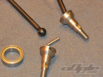
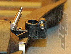
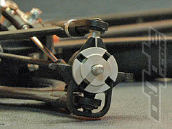
The business end consists of only 3 parts, the main shaft, the axel, and a pin. The pin simply goes through the axel and shaft and the drive shaft is able to pivot on the pin in all directions. The pin is then held in place by the bearing in the hub, which covers it at both sides, very simple and neat.
|
 |
| Plastic sliders, glued in place. |
 |
| Business end of shaft is safe from dirt. |
|
You begin to realise by this point how brief in areas the manual is, some parts you are guided through, like the top wishbones, others like the drive shafts or lower wishbones you are given a exploded view of the parts and that's it.
Sometimes you are reading one part of the manual for the next step, and suddenly you realise half the car (ok, not quite) has been finished without any mention in the manual !!!! |
|
Front suspension is similar to the rear, first job is to set some short pivot pins into the top gearbox moulding to support the top wishbones, these need pressing really well into the gearbox top otherwise the suspension will bind.
Unfortunately its a similar story to other post-mould drilling as one side seems centred and the other side is off centre by half a mm or so, its not a lot and it most likely wont affect the handling at all, but these sort of things don't feel quite right.
Corresponding pins bolt through the front carbon fibre pivot pin plate and secure the upper wishbones front and back.
Lower wishbones mount up similar to the back, with a long pin going through the wishbones and lower chassis holding it all together. |
|
 |
 |
Pressing the suspension pin into the gearbox. |
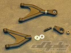
Front upper arms |
Front arms mounted |
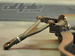
The rockers mount up next, these mount onto pivot shafts that are screwed into the gearbox top, as I said earlier, this is a replacement gearbox top as the holes were misaligned and caused the rockers to actually hit each other.
Push rods link the lower wishbones to the rockers, these screw into holes which are drilled into the wishbones after moulding and again seem to be somewhat random in their positioning although I cant see it affecting performance. |
|
|
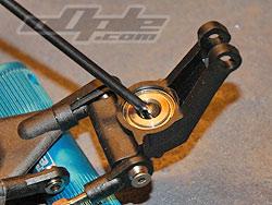
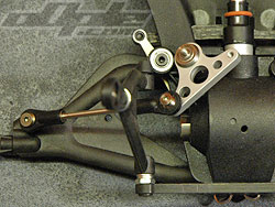
Front uprights do the job of the steering knuckle also, instead of separate items like on most 4wd cars, and pivot on large ball joints at the end of upper and lower arms.
These ball joints are TIGHT and definitely add a lot of resistance to the movement, both steering and suspension action are affected. I was told to "pinch" the cups with some pliars, which streches the plastic and frees things up, it seemed to work slightly. |
 |
|