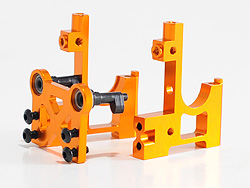
The three parts need screwing together on a flat surfance.
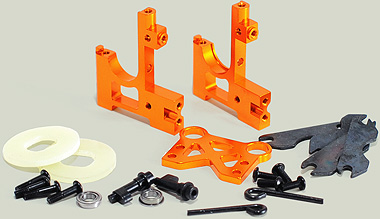
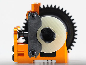
Fibreglass brake discs
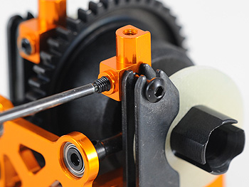
Simple stamped steel plates clamp the discs for stopping duties.
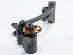
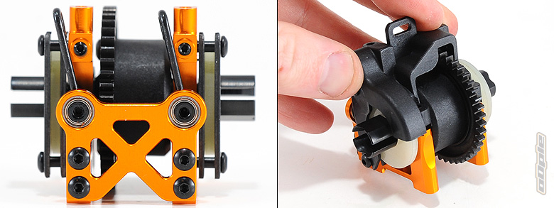
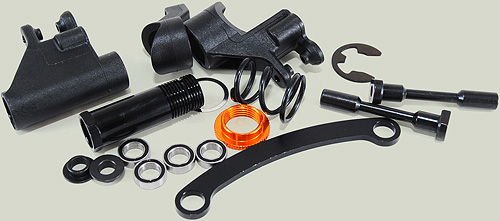
The centre diff mount is assembled from three main parts, all machined from alloy and orange-anodised. Tasty.
I found the instructions weren’t really clear at this point, since the brake cams need installing during assembly and it’s not entirely clear which way round they should be facing but a quick check of the JQ website explains the mistake in the manual and mentions the very first cad image of the centre mount is the correct way with one facing up and the other down.
Grub screws help lock the brake pad screws in place.
It’s pretty easy to build the centre diff mount skewed since it relies on being screwed together correctly (there’s no interlocking of components to help keep things square. I placed the assembly on my desk surface and tightened all the screws a little at a time to ensure it was built straight.
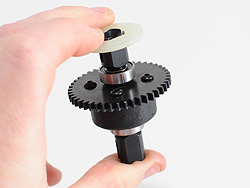
Braking duties are taken care of by a pair of thick fibreglass discs clamped by pressed steel plates - simple and effective.. The manual reccomends between 0.5 and 1mm play in the pads, though later experience would suggest at least 1mm of play is best - since we had a problem with the brakes locking-on for some reason - running around 0.5mm.
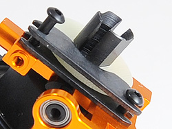
A mouled cover holds the differential in place and helps shield the brakes from nasty fuel-juices and other debris which could contimate them and effect braking. Oh, and it stops you foolishly getting your fingers chewed up in the gears.
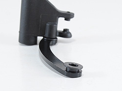
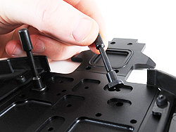
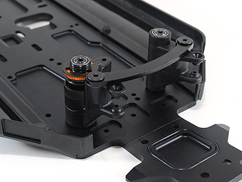
The steering on the JQ car is taken care of by a pair of vertical bellcranks joined together by an alloy ackerman link. I found it very hard to push the steel top-hat washers into the alloy ackerman link but slowly screwing things in place pushed the inserts in place whilst unwinding the screw quarter of a turn made things super-smooth and slop-free.
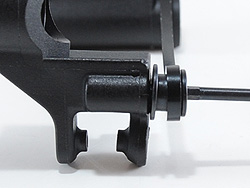
A giant E-clip secures the threaded servo saver and stops it from backing out - I guess you can tightent this servo saver some more but my fingers had already had it and I was sweating and needed a break. Getting your fingers round the adjuster whilst the E-clip is in place might be a bit tricky however.
The steel insert was a tight fit
...But screwing things together pushed it home nicely
A large E-clip stops the servo saver from unwinding
The steering slips onto a couple of lightened (reduced diameter in the middle) steel posts that are attached to the main chassis plate. The front and rear ends that are now pretty near complete follow - each end locking onto the main chassis plate to keep it square before being clamped in place by four 4mm countersunk screws per end.
The steering posts
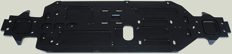
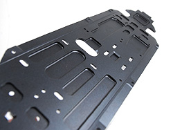
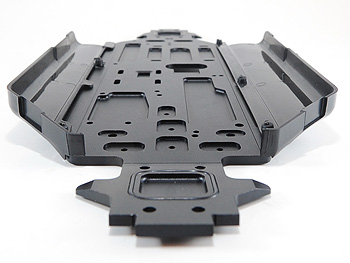
Lots of lightening on the chassis plate
My 'limited edition' car came with a special number - 16
The main chassis itself is a stealthy black-anodised thing of beauty. The only worry I have is what it'll look like after it's seen a race or two - the black will show up the scrapes much more than the usual lighter-coloured anodising finishes.
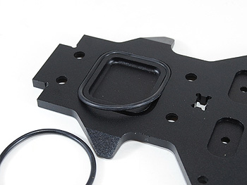
Rubber o-rings sit inside recesses at the front and rear of the chassis where the gearboxes will eventually sit - these sit against the bottom of the open gearboxes to prevent any nasty stuff getting in there, effectively sealing them whilst still allowing the diffs to sit down into the chassis as low as possible.
O-rings seal the gearboxes against the chassis
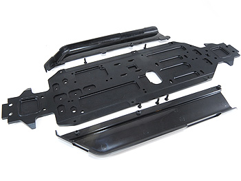
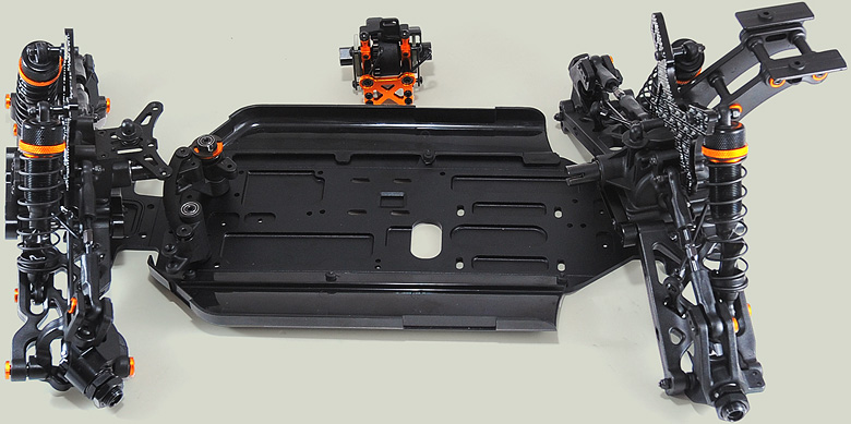
Side-pods protect the gear inside
Big moulded side guards attach to either side of the chassis - widening the once sweet narrow chassis to the usual bulky 8th scale proportions we all love. The front & rear ends that were completed earlier in the build can now be attached to the chassis, using four M4 countersunk screws.
Above: The front and rear ends along with the centre diff await connection to the chassis.


 The steering on the JQ car is taken care of by a pair of vertical bellcranks joined together by an alloy ackerman link. I found it very hard to push the steel top-hat washers into the alloy ackerman link but slowly screwing things in place pushed the inserts in place whilst unwinding the screw quarter of a turn made things super-smooth and slop-free.