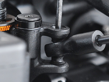
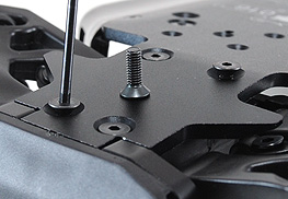
The front end wouldn't sit properly on the chassis for me at first - the rear brace on the front assembly needs to sit around the leading edge of the chassis but it's not really obvious when this happens since the overlap is small.
I thought things were fine and screwed the front end down only to discover the steering hit the drive cup from the front gearbox and the upper deck didn't quite meet the tops of the steering.
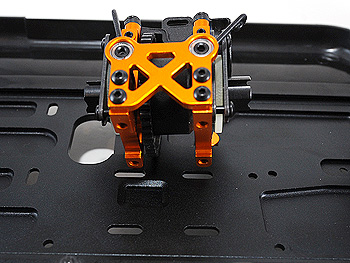
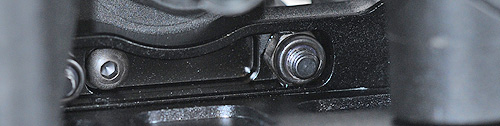
Getting the front-rear brace to overlap the chassis is vital
The upper deck didn't meet the steering at first.
The steering hit the drive cup.
The front-rear brace LOOKED like it was installed correctly - but wasn't.
I took things apart to try and figure it out and get things to sit properly. The tolerances are probably a bit fine - at least on my kit anyway, as it felt more of a push fit rather than simply dropping into place.
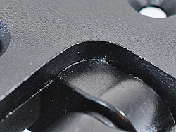
This is what it should look like when the front-rear brace is sitting properly
Once I'd put things together properly - everything lined up fine and the steering JUST misses the drive cup despite being very close. It's all good in other words and I'm just a bit stupid.
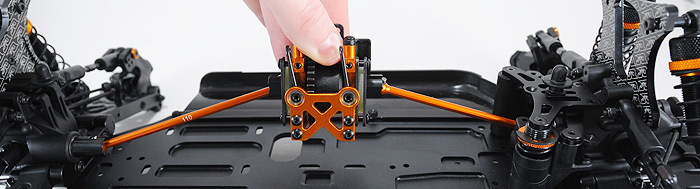
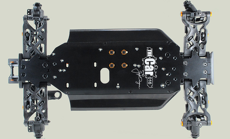
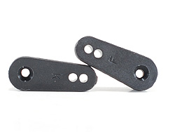
Chunky plastic braces attach to both front and rear gearboxes to tie them to the chassis plate. These should give a bit more flex than alloy items and make for a more forgiving car.
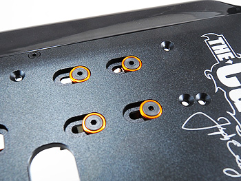
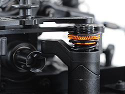
The centre bulkhead / diff mount on THEcar has a unique feature - the ability to move fore/aft by several mm’ to match the engine position.
The engine fore/aft position is altered by using different mounting holes in the engine mounts & turning the mounts 180 degrees for more options. A total of four positions appear to be available between fully forward and fully-back.
The centre diff screw holes are slotted
Centre diff position can be adjusted to suit.
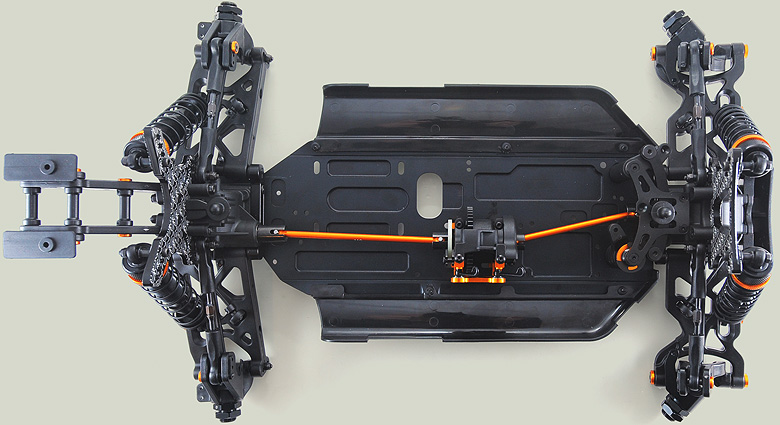
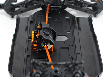
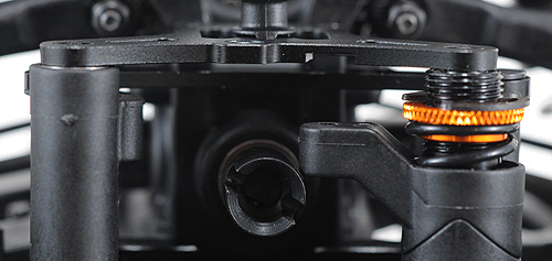
The centre diff mount transmits power to either end via lightweight orange (what else!) anodised alloy dog bones. The dogbones allow the greatest possible fore/aft positioning for the centre diff.
Above: The offset transmission line can be seen - which allows the engine to sit centrally.
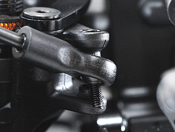
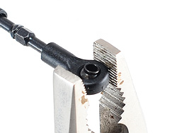
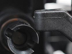
The screw fully and completely skewed off to the side :(
Lining things up with a driver - even then it takes patience
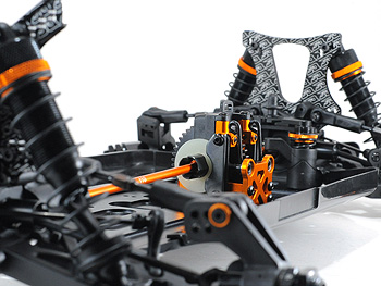
The steering links are added at this point in the manual - with all the parts already attached to the main chassis. I’d definitely suggest adding these links to the steering bell cranks earlier in the build since they are - or were in my case - a really tricky fit.
KO / Sanwa and Futaba / Ace / AE horns are supplied for the steering and throttle.
The steering ball cups were TIGHT until they got a squeeze
The screws that secure the inner ends of the links go through the plastic steering crank mouldings that sandwich the link - the problem I found was that by the time the screw got to the other side the screw was off to the side no matter what I did.
In the end I lined things up with a driver through the lot before carefully and slowly inserting the long screw. Even then it was really hard to get the screws in square - I think it’s possibly the common theme with the JQ car that all the screws into plastic are tight and the holes could do with widening slightly to make entry easier.
The steering link ball cups I found to be much tighter than those used on the rest of the car - too tight in fact. I used some pliars to squeeze them and loosen things up - tight is better than loose any day.


 Chunky plastic braces attach to both front and rear gearboxes to tie them to the chassis plate. These should give a bit more flex than alloy items and make for a more forgiving car.